1. Introduction
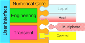
1.1. WANDA domains
The sophisticated software architecture of WANDA 4 enables the user to access physical domains such as heat transfer (density, viscosity, temperature) and multiphase systems. The Liquid module incorporates the former WANDA 4 version; the well-known User Interface and other successful parts are basically unchanged.
1.1.1. WANDA 4 Liquid
WANDA Liquid provides a wide variety of components from which most hydraulic systems can be built for each type of fluid, no matter what size or operational conditions of the network. WANDA Liquid includes amongst others:
Accurate head loss of T-, Y- and X-junctions (Idelchik)
Newtonian and non-Newtonian fluids (slurry friction model)
Active components: pumps, (control) valves and air vessels
Filling of pipelines
Free surface pipe/channel component
Transition of partial filled pipelines into a completely filled, “waterhammer” sensitive system
Advanced components: e.g. turbine and dynamic check valve
1.1.2. WANDA 4 Heat
Heat transfer and monitoring the temperatures in a liquid system is realised with Wanda Heat, making it an interesting module for urban district heating networks and process industry. WANDA Heat calculates mass flow rates, pressures and temperatures.
Full temperature dependent fluid properties
Heat transport due to flow
Heat transfer to and from the surroundings
Heat transfer by dedicated components (heat exchangers)
Heat generation by friction
1.1.3. Control
WANDA Control is a very powerful module supporting all other modules with the simulation of the complex operation of systems. The control module allows the hydraulic system to be linked to a control system. This allows the user to evaluate the effectiveness of different control philosophies on the hydraulic system. Notable features include:
Advanced pumping station controllers including parameters for ramp-up time, minimum speed etc.
Activation of valves, pumps, etc
Varying of boundary conditions (pressure head or discharge)
Sensor and generators (logical or numerical output)
Conditional block (IF-statements and switches)
Logic operators (AND, OR, exclusive OR, NOT)
Numeric operators (add, multiply, functions, etc.)
Continuous controllers (PID-controllers incl. start/stop)
1.2. Modelling aspects
1.2.1. From real world to mathematical model
In (numerical) models such as WANDA, only separate parts of the real world are included that can be considered more or less independent of external influences. At the boundaries of a model interaction with the outside world takes place. The modeller must decide based on experience what level of detail to include in the model. This process of schematization of the real world results in a model of the parts of the real world that are of interest to the user. If the modeller makes the right decisions, the model can be used to simulate events that (can) occur in the real world. In this way phenomena in the real world can be studied without the need of expensive or even impossible changes to the (pipeline) system.
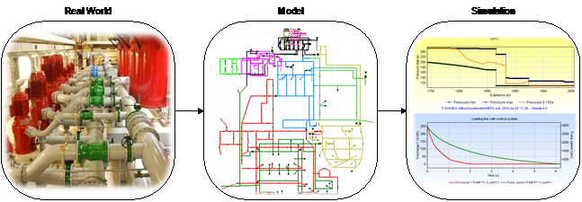
A simulation is an event in the model that corresponds to the real world
WANDA helps the modeller to build a solid model for pipeline systems quickly. The modeller can build a model by connecting symbols of common hydraulic components to each other. The result is a scheme of symbols and lines that represent the part of interest of the real world. The symbols represent mathematical equations in WANDA and the lines exchange information
1.2.2. Hydraulic diagram editor
WANDA uses iGrafx® FlowCharter® as diagram editor. This program is part of the delivery and fully integrated in the WANDA software. iGrafx is a division of Corel®.
iGrafx® FlowCharter® is a full-featured, easiest to use process analysis and modelling tool to help organizations understand and improve (business) processes. A graphical representation of processes allows people to easily comprehend information and quickly focus on the bottlenecks and issues in a process.
1.2.3. Components and galleries
The symbols in the WANDA diagram are called components. The components contain mathematical models which are expressed in equations. Combining the mathematical models creates a hydraulic model.
For each WANDA domain there is a library of components that can be applied to build the hydraulic model. This library is called the gallery. Each domain has is own gallery.
For each domain this manual contains a separate chapter where all available components are described.
The figure below shows some examples of the galleries.
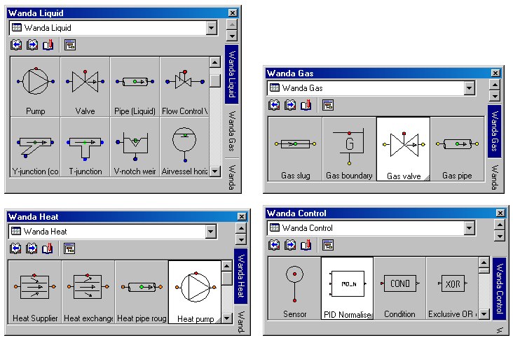
Some components in different domains are very similar but the equations will be different. In the Liquid domain the main variables are H (head) [m] and Q (discharge) [m3/s], in the Heat domain the main variables are p (pressure) [N/m2], M (massflow) [kg/s] and T (temperature [ºC].
Each component has 1 or more connect points. For each connect point the main variables are calculated. The components are connected to each other by connection lines. To prevent the user for connecting components from different domains each domain has his unique connect point colour (Liquid: blue, Heat: orange).
NOTE: Since the introduction of the WANDA software the group of hydraulic components and nodes are called H-components and H-nodes, With the introduction of new domains like Heat, each domain has his own group of components and nodes. Therefore it is better to use the general name of physical components and physical nodes which can be split into liquid and heat components and nodes. The annotation H-component and H-node as many times used in this manual must be read as pHysical component and pHysical node
1.3. Calculation modes
1.3.1. Time scales
A distinction can be made between several hydraulic aspects considering time scales. Therefore, we will distinguish two different modes: the Engineering mode and the Transient mode.
1.3.2. Engineering mode
In Engineering mode only steady state calculations are done, assuming that there are no changes in time and all variables are constant. The fluid is considered incompressible.
WANDA Engineering has been developed to support the most common activities in the hydraulic design of any piping system:
Design of arbitrary hydraulic systems using a wide variety of available hydraulic components.
Quick design using flow-prescribing components (pumps, valves, taps, etc.). Pump speeds, valve positions, tap head losses, etc are calculated. Flow and pressure balancing.
Reliable design using component parameters from your own (company) database.
Evaluation of pipe diameters, hydraulic gradients, flow velocities.
Calculation of the system characteristic to support pump selection.
Calculation of the energy consumption and efficiency of a pumping station
1.3.3. Transient mode
The Transient mode allows unsteady flow conditions to be investigated.
Wanda computes all different kind of unsteady phenomena, varying from extended time simulations until fast waterhammer events, including cavitation.
To change from steady to unsteady flow regimes it is necessary to change the behaviour of one or more components. Therefore some components are active which means that certain settings can be changed in time by the user or by control components.
Quasi-steady (extended time simulation)
Quasi-steady calculations can be considered as a number of independent steady state calculations, which happen to be following each other time. Although the conditions may change with time (e.g. different discharge patterns or valve positions for each time step), each calculation is independent from earlier solutions. For instance engineering tools like Epanet use the quasi-steady approach to determine the water levels and residence time in reservoirs during a certain period of time (day or week).
WANDA uses the quasi-steady approach to calculate the pipe friction at the new time step. WANDA Control uses the quasi-steady approach as it ‘measures’ at the old time step to determine the control-actions at the new time step.
Waterhammer (Pressure transients)
Due to abrupt changes in the flow conditions (valve closure, filling of pipeline or reservoir) pressure waves develop, which travel through the pipeline (surges). As the fluid and containing pipeline are compressible, the pressure wave needs time to travel from one end of the pipeline to the other end. These pressure waves are very quick phenomena (transients) with wave speeds up to over 1000 m/s.
In Transient mode WANDA calculates the pressure waves in all waterhammer pipes. The fluid in rigid column pipes is considered incompressible, resulting in an infinite wave speed.
Cavitation
Pressure waves and abrupt variations in the pipe profile (e.g. a partially closed valve) can result in substantial changes in pressure. When the fluid pressure drops below the fluid vapour pressure, cavitation can occur. Liquid becomes gas and as gas is more compressible than liquid, the amount of gas in the pipeline changes the flow conditions.
In WANDA the effect of cavitation is included as it recalculates the flow conditions at each time step depending on the pressure and fluid properties.
1.4. Validation
The numerical models in WANDA and its predecessors have been validated since the seventies. For these validations special test rigs were build (e.g. 1000 m long cavitation test rig) or field measurements are used. Component modelling is based on physical performance testing in the hydraulic flow laboratory of Deltares as well as on site testing. Deltares’ reputation and decades long experience of fluid dynamics are a guarantee for the high quality of this powerful simulation software package.
A benchmark analysis has been conducted in a European project between 1998 and 2002, in which WANDA and three other commercially available transient simulation software tools have been benchmarked against a selected set of field and lab data.
The validation report is available via http://wanda.deltares.nl
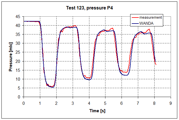
Validation results from measurement and WANDA simulation
1.5. WANDA 4 main features
Branched and looped systems,
Steady flow,
Transient flow,
Free surface flow (optional),
Cavitation,
Control module (optional),
System optimisation module,
Over 100 different components, supporting rapid design calculations,
Powerful pipe model with several friction models including local losses,
Interrupting and resuming of simulations,
Graphical user interface with intuitive look and feel
Simple and flexible operating principles,
Choice of different unit systems (SI, UK, US, user units),
Your own (company) database of hydraulic component data
Graphical and tabular presentation of time and distance functions of all hydraulic output results
Animation of the dynamic simulation results
1.6. To whom is WANDA 4 a useful tool?
In the years following the introduction of WANDA in 1994, it has been licensed to many well-known companies and it has been used for diverse applications related to:
(Process) plant piping,
Sewage transport pipelines,
LPG pipelines,
Long distance crude oil pipeline transport,
White product conveyance systems,
Oil loading and off-loading pipelines,
Fire fighting systems,
Drinking water networks,
Water treatment facilities
Cooling water systems,
Heat transportation systems,
Gathering and distribution networks,
Chemical pipelines,
Slurry transport and sludge handling
1.7. How to use this manual
In chapter 2 the WANDA user interface is described. This part is based on the Wanda 4 Liquid module. The basic user actions like creating a hydraulic model, specifying data and retrieving result in charts and tables applicable for all other modules.
Chapter 3 contains the main theory necessary to understand the numerical background of the program.
For each physical domain a separate chapter is used where all individual components are described.
1.8. System requirements
In order to run the Wanda software, your computer must meet the following requirements:
Operating system: Windows 10, 11
At least 1 GB of memory
At least 512 MB free space on hard drive
The user account must have sufficient privileges to read from the Wanda installation directory
The user account must have sufficient privileges to write to the document directories, user profile and Windows TEMP directory
1.9. About Deltares
Deltares owns a flexible large-scale, Multi-phase Flow Facility (alpha-loop) in order to enable investigations in a wide range of academic and industrial multi-phase research topics. This includes studies of gas blow out, pressure relief valves and air valves. The alpha-loop allows for single-phase (water), two-phase (water, air) and three-phase (water, air and sediment) studies in a pipeline system of arbitrary shape.
1.10. Technical Support
Deltares
Boussinesqweg 1
P.O. box 177
2600 MH Delft
The Netherlands
Wanda community Wiki: wanda.deltares.nl
internet: https://www.deltares.nl/en/software/wanda/
Software Sales team:
telephone: +31(0)88 335 8188
e-mail: software@deltares.nl
Software Support team:
Mon-Fri 8.30-17.00 CET
telephone: +31 (0)88 335 8100
e-mail: software.support@deltares.nl