5. WANDA Control
wanda control is a further development of the wanda hydraulic analysis tool. It enables the user to simulate a wide variety of control systems added to the hydraulic system. This is performed by superimposing a control network over the hydraulic network. The control network can respond autonomously to events and values occurring elsewhere in the system. The added value of wanda control lies in the far more realistic simulation of the dynamic behaviour of the controlled system than with conventional control simulation packages. Another added value lies in the possibility of having scenarios simulated in a far more automated way then wanda without control.
The control system is schematised as a network of sensors, signal lines and control components (“blocks”).
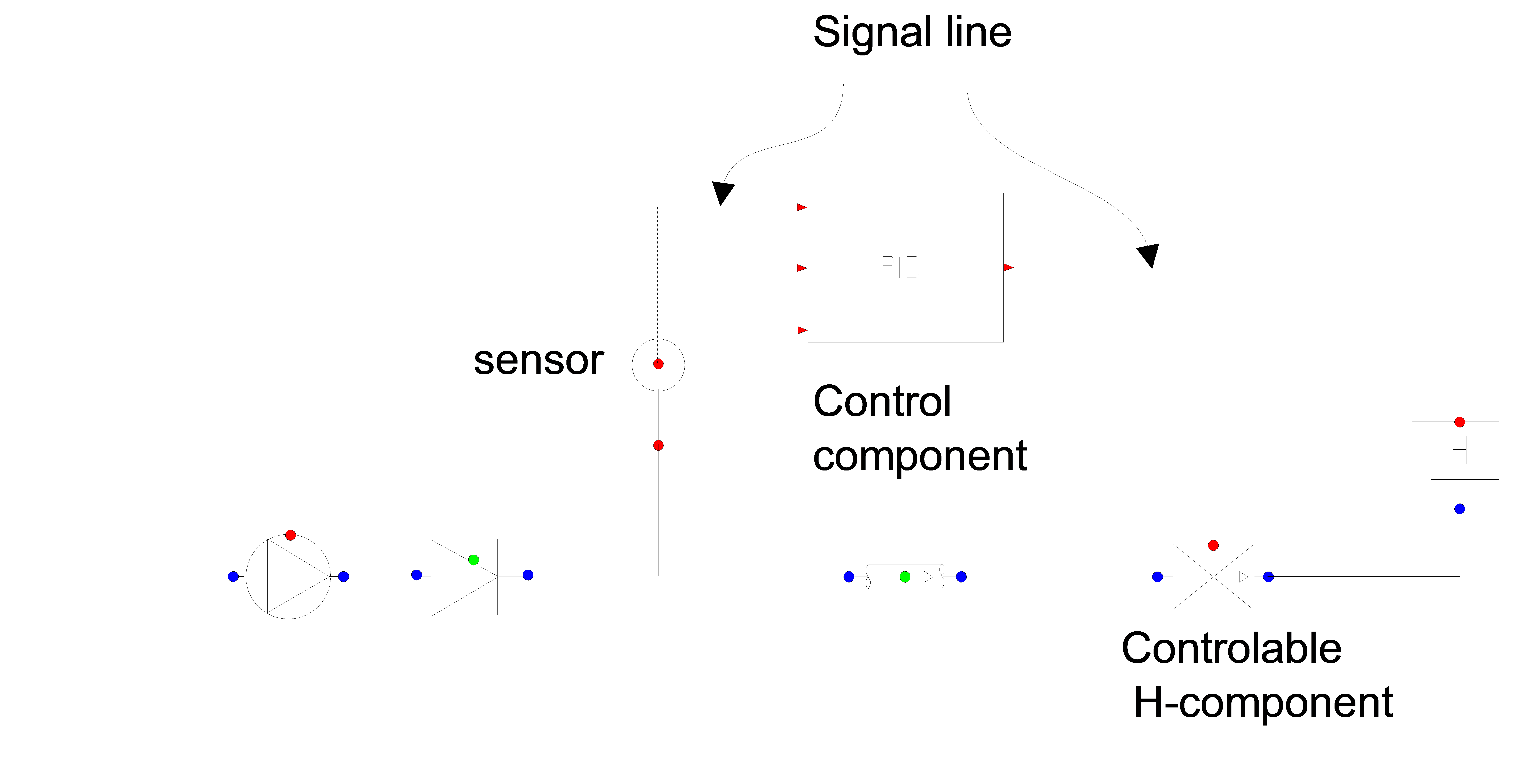
Fig. 5.1 Example of a system with control components
These terms will be defined more exactly in the next section.
There are basically two types of control systems:
Conditional actions
Continuous control
The former generates an event, like start of a pump, closure of a valve, etceteras. The latter generates a value for the controlled variable such as valve position or pump speed.
Contents
- 5.1. Modeling aspects
- 5.2. Definitions
- 5.3. Overview Control components
- 5.4. 2COND
- 5.5. ABS
- 5.6. AND
- 5.7. BIAS
- 5.8. CON
- 5.9. COND
- 5.10. COND2
- 5.11. DELAY
- 5.12. DIV
- 5.13. FUN
- 5.14. GAIN
- 5.15. INTGRT
- 5.16. LCON
- 5.17. LCS
- 5.18. LCS2
- 5.19. LDELAY
- 5.20. LTAB
- 5.21. LtoN
- 5.22. MAX
- 5.23. MAXVAL
- 5.24. MIN
- 5.25. MINVAL
- 5.26. MOD
- 5.27. MOVAVG
- 5.28. MSP
- 5.29. MUL
- 5.30. NOT
- 5.31. OR
- 5.32. PID
- 5.33. PID_N
- 5.34. PIDSS
- 5.35. PIDSS_N
- 5.36. POW
- 5.37. RAMP
- 5.38. RDFILE
- 5.39. SELECT
- 5.40. SENSOR
- 5.41. SFUN
- 5.42. SIGN
- 5.43. STAB
- 5.44. SUB
- 5.45. SUM
- 5.46. TAB
- 5.47. TAB2
- 5.48. TIME
- 5.49. TRUNC
- 5.50. WAVE
- 5.51. WRFILE
- 5.52. XOR
- 5.53. Examples