5.46. TAB
Purpose
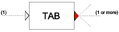
Generates a time dependent numerical value which can be used by other components. Mono-directional.
Procedure
The TAB component is similar to a standard hydraulic action table, with only one difference. The time in the ‘action table’ is relative to the instant at which the input signal becomes TRUE (=1). When the input channel becomes FALSE (=0), the output remains constant until the input signal becomes TRUE again, after which the table will resume from its present value. Hence, the table is mono-directional.
Parameters
Parameter |
input |
unit |
range |
default |
remarks |
|---|---|---|---|---|---|
Table type |
Valvepos/ pumptsp/ boundhth/ boundqtq/ CtrlActn |
CtrlActn |
This type is not used anymore; type will be ignored |
||
Action table |
table |
Remarks
If no logical signal line is connected to the input channel a value of TRUE is assumed. In such a case the TAB component is similar to a standard hydraulic action table. Because the control system has a delay of one time step, the point in time of TAB is corrected with -dt to act like the hydraulic action table. As a consequence of this shift the TAB interpolates in steady state between the 1st row (t=0) and 2nd row (t=T1).
Examples
Figure 1a presents the input ‘action table’ for the TAB component. Figure 1b shows the output of TAB if no conditional control is connected to the second input channel.
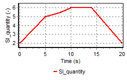
Fig. 5.46.1 input TAB
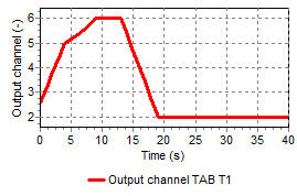
Fig. 5.46.2 output TAB (be aware of -dt shift)
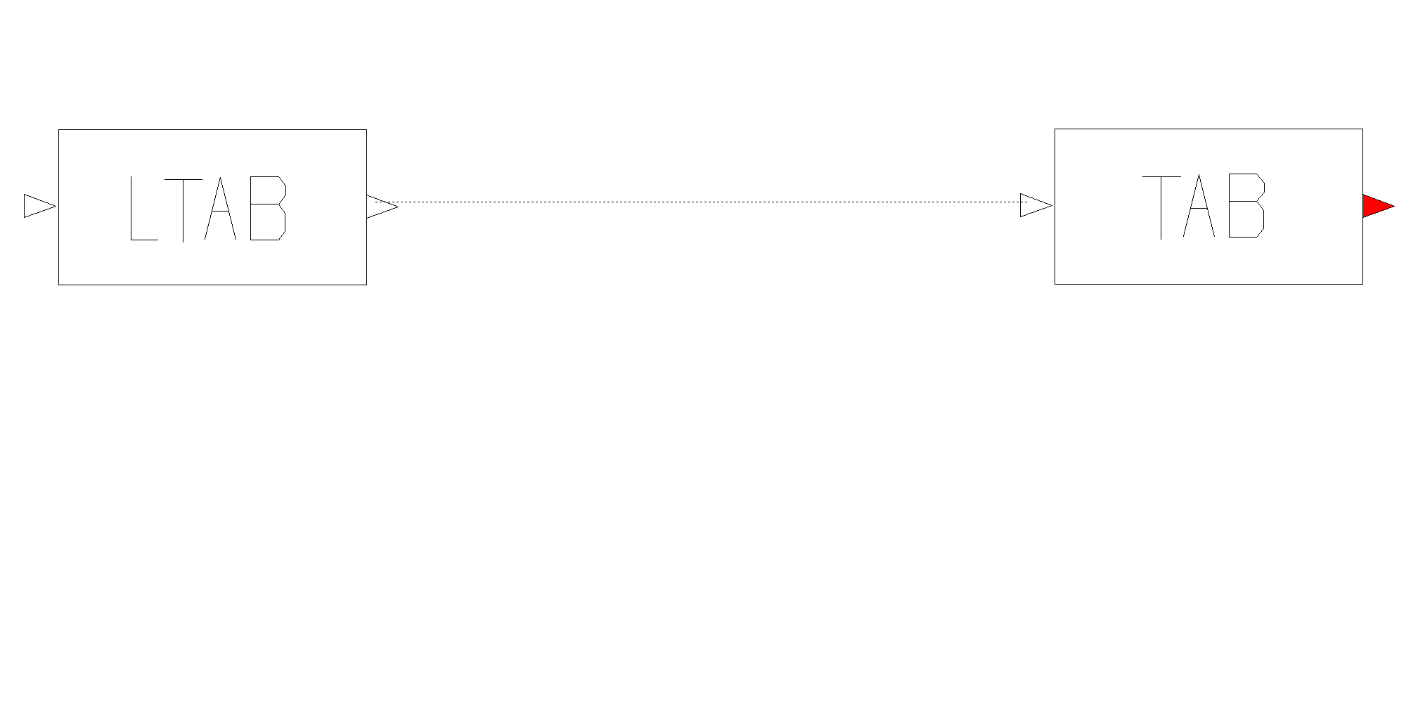
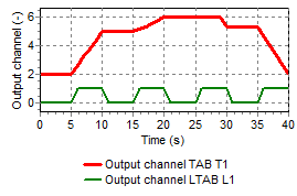
Figure 2 shows the output of TAB (thick red line) together with the logical input signal (thin green line), specified by a LTAB component.