5.48. TIME
Purpose
Outputs the model time at every time-step.
Procedure
None
Parameters
None
Remarks
None
Examples
Figure 1 presents an example where the TIME component is used to switch a pump off between 5:00 and 21:00 and on between 21:00 and 5:00 every day. Figure 2 (a & b) shows the output of the MOD and OR component for a simulation duration of 1 week.
Component TAB2 is used to translate logical output to a pumpspeed including start/stop time in 5 s. Figure 3 shows the pump speed.
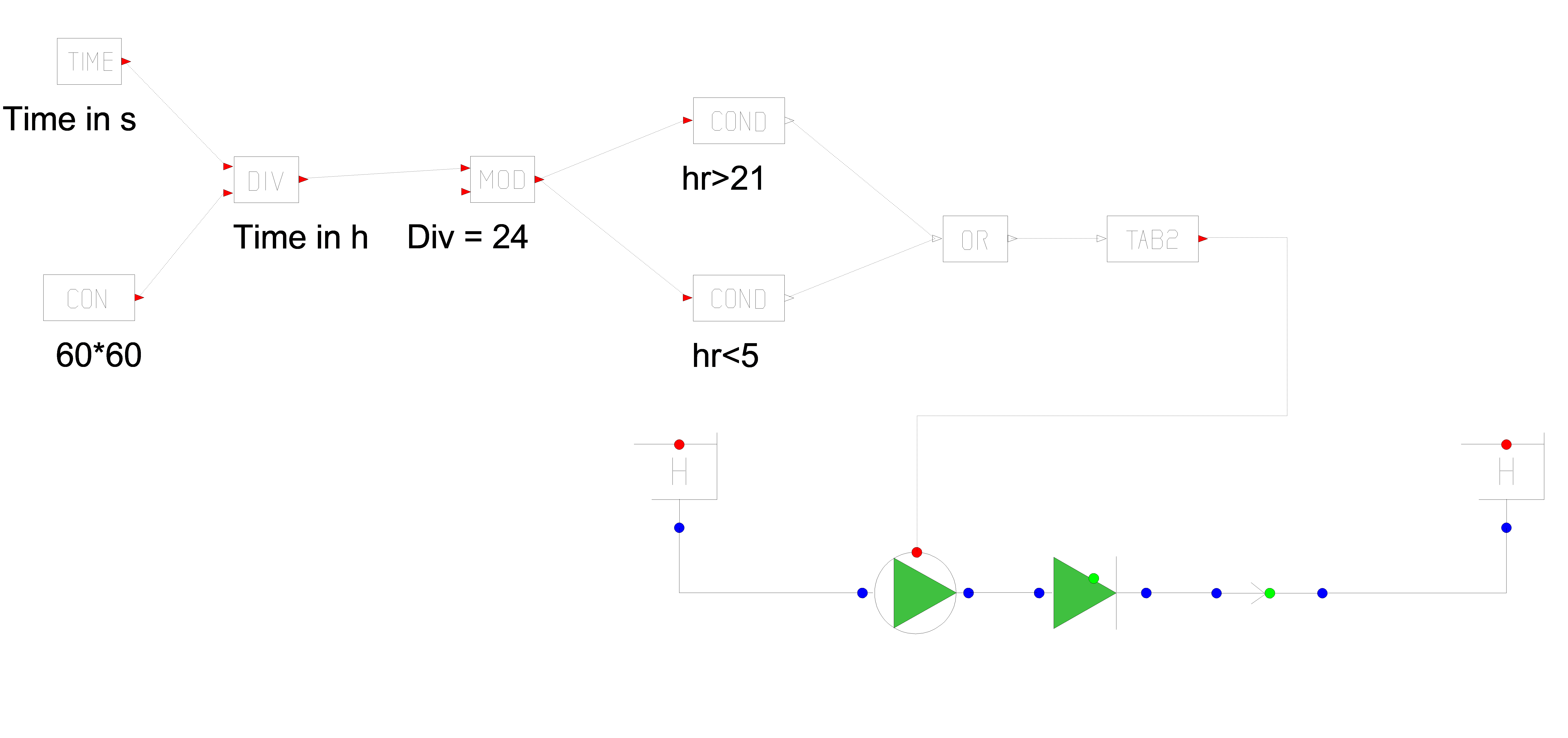
Fig. 5.48.1 Control scheme to operate a pump each day between 21 h and 5 hr
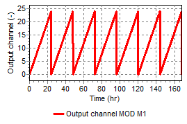
Fig. 5.48.2 Output of Modulo function
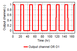
Fig. 5.48.3 On/Off signal for Pump
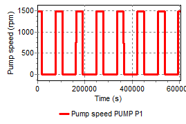
Fig. 5.48.4 Pump speed