5.53. Examples
In this chapter a few illustrative examples will be discussed to demonstrate some of the possibilities of wanda control. The examples are part of the WANDA set-up (see subdirectory WandaExamples).
5.53.1. Tripping pump
In the figure below a very simple system is depicted. A pump drives a transport line, which is terminated by a shut off valve. When the shut off valve starts to close the pressure at H-node D will rise, as well as the pressure in pipe P1. The pressure is measured by a sensor and transmitted to the C-component COND(itional action).
The pump must be turned off if the pressure in H-node D exceeds the set pressure of 2 barg during 2 seconds.
The parameters of COND are as follows:
logical operator: LT
set value: 20000 [-]
reset time (true) (Pump = on): 0 [s]
reset time (false) (Pump = off): 2 [s].
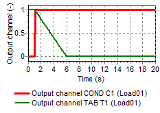
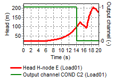
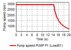
As soon as the measured pressure has risen above 2 barg for at least 2 seconds (reset time), the output will become FALSE. This logical signal is fed into the pump of drive type TRIP. For this type of pump a control signal becoming FALSE is interpreted as the signal to start the tripping. The result is thus that, when the pressure at H-node D goes through the 200000 value (Pressure in N/m2 corresponding with 2 barg) at T=10 seconds, the pump will trip at T=12 seconds.
5.53.2. Loading Arm
The figure above shows a loading line from tank 1 to ship B. If the back pressure drops below a certain set level, e.g. in case the ship breaks loose, the conditional action closes valve V1. A pressure wave is then propagated through pipe P1, which is monitored by a sensor just downstream of the pumping station. If the set pressure is exceeded the pumps are switched off.
5.53.3. Flow control valve
To demonstrate the operation of a PID-controller a simple flow control system is shown in the figure below.
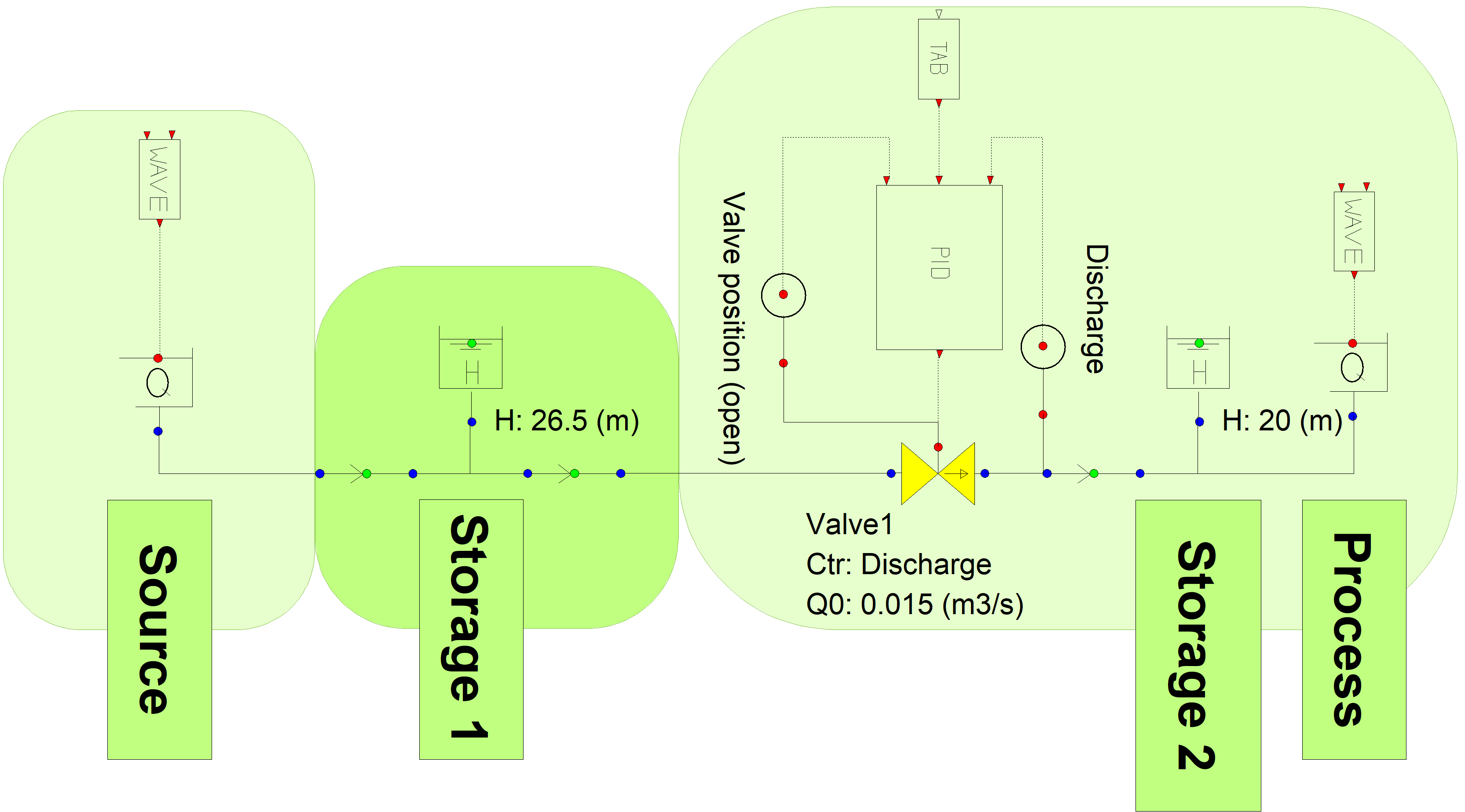
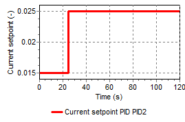
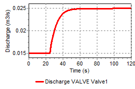
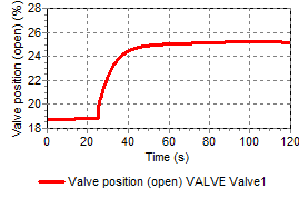
In steady state the control scheme must be in balance too. The setpoint of the flow control valve is 15 l/s (because the SI-unit of discharge is m3/s, the specified property value will be 0,015) To achieve this, the initial setting property of the valve is set to ‘Discharge’, with an initial discharge equal to the setpoint of the PID controller. As a result of the hydraulic calculation, the valve position will be calculated. The valve position is measured with a sensor and fed back into the PID controller as the initial value of the integrator, ensuring that the control system is in balance with the hydraulic system.
At the begin and end of the system a WAVE component is used to introduce some flow disturbances.
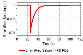
At t = 25 s the setpoint is changed from 0.015 m3/s to 0.025 m3/s using the TAB-component. The PID controller adjusts the valve position to reach the new setpoint.
5.53.4. Flow control valve with start/stop conditions
To demonstrate the operation of a PIDSS-controller the flow control system similar to the previous example is extended with an open/close condition.
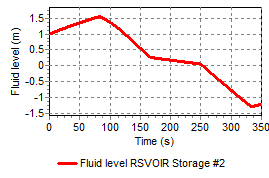
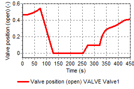
In the scheme below the flow control valve fills storage tank 2. If the tank is full enough the valve must be closed and if the tank becomes empty the valve must be opened. During operation a required flow must be achieved.
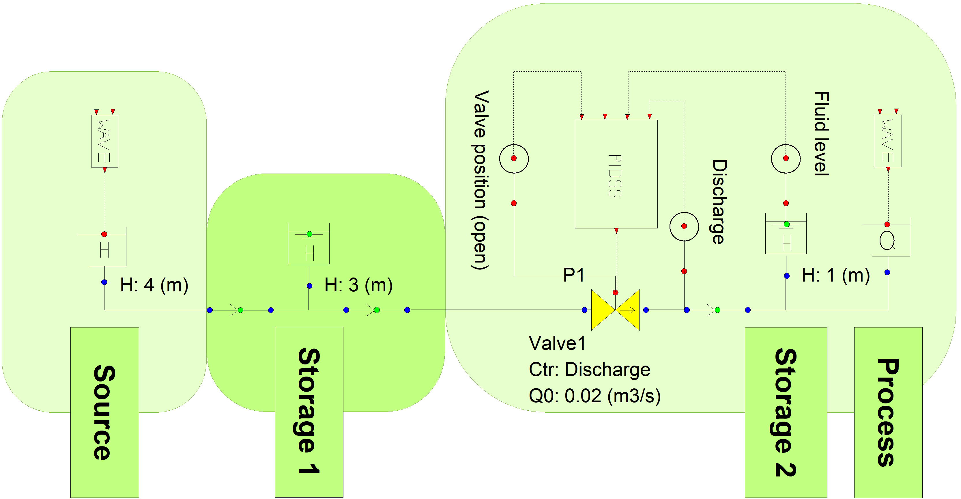
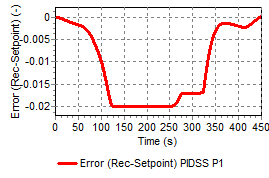
The PIDSS controller has an extra input signal, which is used to switch the controller on and off at a certain value.
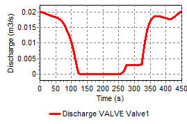
The discharge setpoint is 0,02 m3/s. The controller switches on and off based on the fluid level in the second storage tank. The ON-level is 0 m, the OFF level is 1,5 m.
5.53.5. Control of a pumping station
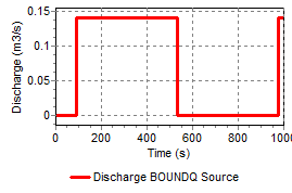
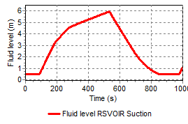
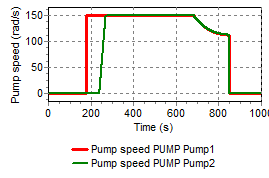
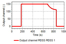
In the figure below a characteristic sewage water transport system is shown. The pumping station consists of two pumps. The system has a discharge controller with a sump-level dependant set-point.
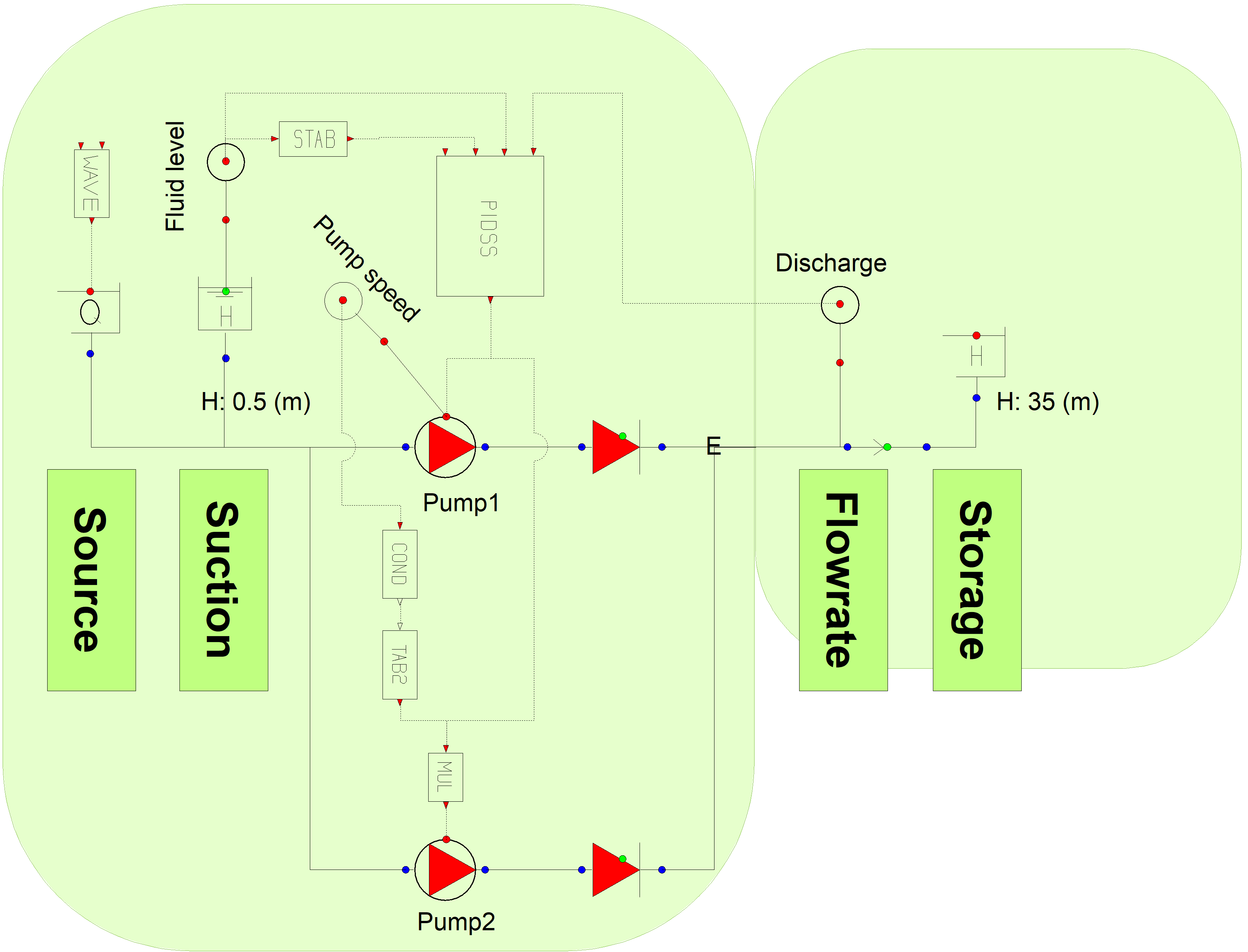
If the capacity of the first pump is not enough to maintain the required setpoint, the second pump becomes in operation.
Pump 1 starts if the level in the sump becomes above the IN-level (3 m) and stops if the level becomes below the OUT-level (0,5 m)
The pumpspeed of pump 1 is measured using a sensor and fed into the COND block. The second pump only starts if the first pump is at it’s maximum speed for longer than 60 s. It runs for at least 3 minutes before shutting down again. This is done via de TAB2 block, which outputs either 1 or 0. The multiplication with the output signal of the PID controller causes the second pump to run