5.40. SENSOR
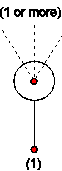
Fig. 5.40.1 Schematic of a Wanda Sensor
Purpose
Measures a quantity from the hydraulic system and sends the values via signal lines to other components.
Procedure
After obtaining the hydraulic solution at each time step, the measured quantity is sent to the output channel.
Parameters
Description |
input |
unit |
range |
default |
Remarks |
|---|---|---|---|---|---|
Sequence number |
Real |
||||
Meas location |
Real |
[m] |
Offset in sensor height |
Remarks
The output channel is located at the centre of the sensor circle.
Sensors can be used to measure hydraulic quantities (eg. head, discharge, velocity) or component specific quantities (eg. valve position, pump speed)
Examples
Figure 3 presents three sensors measuring different quantities along a pipeline:
The left sensor is connected to a hydraulic node and is set to measure pressure head.
The middle sensor is connected to the downstream end of a pipe and is set to measure discharge (the sensor could also have been connected to the upstream end).
The right sensor is connected to a valve and is set to measure the head loss across the valve.
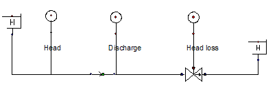
Fig. 5.40.2 Schematic of a Wanda model where three sensors measure different quantities on a pipeline.