5.18. LCS2
Purpose
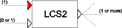
The Level Control Switch (LCS2) can be used to switch on at one level and to switch off at another. For example:
Pump sump (On-value > Off-value): When the level in the collection reservoir exceeds a certain value the pump is switched on. When the level drops below a certain value the pump is switched off.
Pressure system (Off-value > On-value): When the pressure in the system falls below a certain value the pump is switched on, to re-pressurise the system. When the pressure exceeds a certain value the pump is switched off.
Furthermore, the LCS2 component can be enabled/disabled depending on the logical input signal.
Procedure
The sense of the operation depends on which of the two values are greater.
On-value > Off-value:
Output will become TRUE if the input signal exceeds the On-value.
Output will become FALSE if the input signal drops below the Off-value.
On-value < Off-value
Output will become TRUE if the input signal drops below the On-value.
Output will become FALSE if the input signal exceeds the Off-value.
The above procedure will only be executed when the logical input signal is TRUE (enabled). When the logical input signal is FALSE the output signal is set to FALSE and the internal reset times are reset.
Parameters
Parameter |
input |
unit |
range |
default |
remarks |
|---|---|---|---|---|---|
On value |
real |
||||
Off value |
real |
||||
Reset time (on) |
real |
[s] |
|||
Reset time (off) |
real |
[s] |
|||
Initial status |
ON/ OFF |
Remarks
Both On/Off-conditions must hold for periods longer than their corresponding ‘reset time’ before the output will switch to TRUE or FALSE. If the conditions do not hold for periods longer than their ‘reset time’ then the output will not switch.
If no logical signal line is attached to the logical input channel, the default value (TRUE) is used. Hence the LCS2 component will behave in the same way an LCS.
Examples
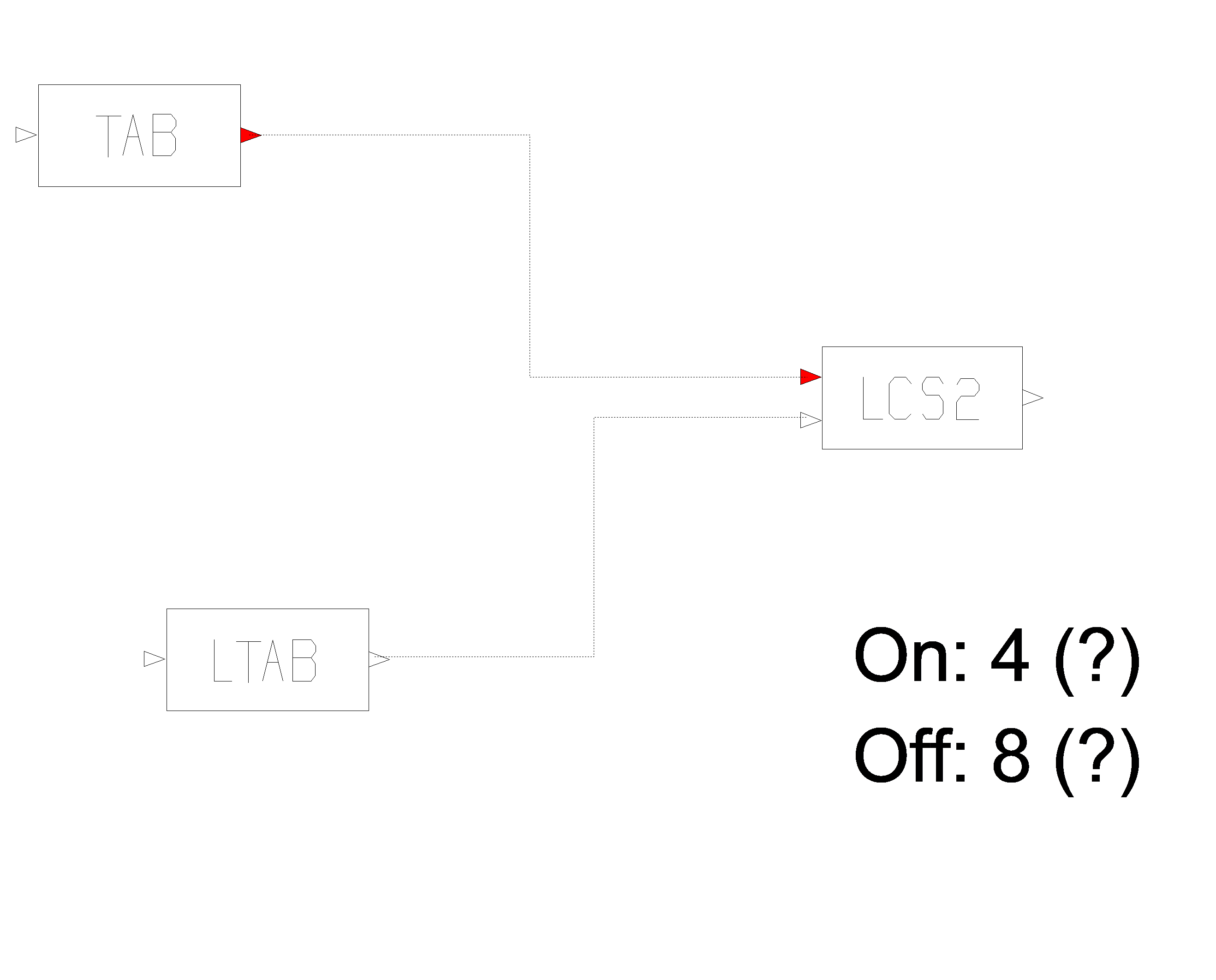
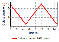
Fig. 5.18.1 Behaviour of LCS2 without LTAB connected
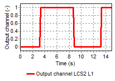
Fig. 5.18.2 Behaviour of LCS2 without LTAB connected
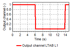
Fig. 5.18.3 Behaviour of LCS2 with LTAB connected
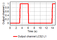
Fig. 5.18.4 Behaviour of LCS2 with LTAB connected
See also LCS.