5.28. MSP

Purpose
The MSP (Multi Stage Pattern) can be used to simulate closure or opening pattern of a valve or pump start/stop with multiple stages including freeze periods.
Procedure
MSP has two input signals and one output signal. The first input signal is a real input signal, which represents for example a time series of pump speeds or valve position. The second input signal is a logical signal. It represents for example the trigger condition for a shut-down.
When the logical input signal is false, the output signal is the same as the real input signal. When the trigger signal becomes true, the output signal is fixed to the to the actual value of the real input. As long as the logical input is true, the change of the output signal follows the MSP (according to the freeze periods, ramp values). When during this time the logical input signal becomes false again, the output signal switches instantaneously back to the actual real input signal.
The MSP control is described by a maximum of 5 stages, each with its own freeze period, ramp speed and end point. Every stage can start with a freeze period in which the output signal is kept constant at the current value (Note that the freeze period can be set to zero). For all stages except stage 1, this value is the end point of the previous stage. When the freeze time has passed, the output value is changed with the specified ramp towards the end point of that stage. When the end point of the last stage is reached, the output is kept constant.
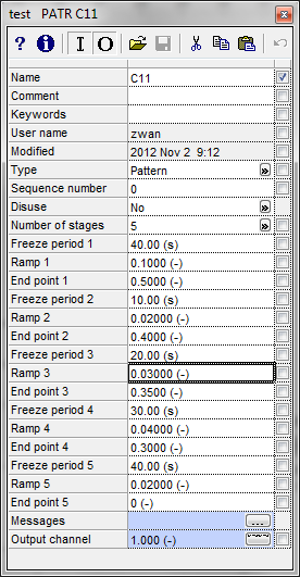
Parameters
Parameter |
input |
unit |
range |
default |
remarks |
|---|---|---|---|---|---|
Number of stages |
1/2/3/4/5 |
[-] |
1 |
||
Freeze period 1 |
Real |
[s] |
0-1e5 |
0 s |
|
Ramp 1 |
Real |
[1/s] |
0-1e5 |
||
End point 1 |
Real |
[-] |
0-1e5 |
||
Freeze period 2 |
Real |
[s] |
0-1e5 |
||
Ramp 2 |
Real |
[1/s] |
0-1e5 |
||
End point 2 |
Real |
[-] |
0-1e5 |
||
Freeze period 3 |
Real |
[s] |
0-1e5 |
||
Ramp 3 |
Real |
[1/s] |
0-1e5 |
||
End point 3 |
Real |
[-] |
0-1e5 |
||
Freeze period 4 |
Real |
[s] |
0-1e5 |
||
Ramp 4 |
Real |
[1/s] |
0-1e5 |
||
End point 4 |
Real |
[-] |
0-1e5 |
||
Freeze period 5 |
Real |
[s] |
0-1e5 |
||
Ramp 5 |
Real |
[1/s] |
0-1e5 |
||
End point 5 |
Real |
[-] |
0-1e5 |
Remarks
The different end points should be either monotonously increasing or decreasing.
If the end points are monotonously increasing the following applies:
If the real input signal is below the end point of stage 1, the MSP control starts with the freeze period.
If the real input signal is equal to or above the end point of stage 1, the control pattern starts immediately (no freeze period).
If the real input signal is equal to the end point of any stage (at freeze level), the freeze period of this stage is not taken into account and the MSP starts immediately.
If the end points are monotonously decreasing the following applies:
If the real input signal is above the end point of stage 1, the MSP control starts with the freeze period.
If the real input signal is equal to or below the end point of stage 1, the control pattern starts immediately (no freeze period).
If the real input signal is equal to the end point of any stage (at freeze level), the freeze period of this stage is not taken into account and the MSP starts immediately.
Examples
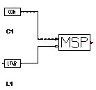
Based on the input and scheme in the above figure several sub-examples have been made with different inputs for a constant (CON) and LTAB.
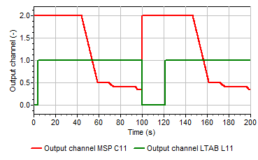
Constant value is assumed to be 2, the logical signal LTAB becomes true at t = 4 s. Because the real value at the time t = 4 sec is 2.0 and therefore larger than the value of End point 1 (0.5), the MSP starts with the first freeze period (40 seconds). After 44 seconds, the output signal of MSP is ramped down according to the given pattern (from Ramp 1 until End point 5).
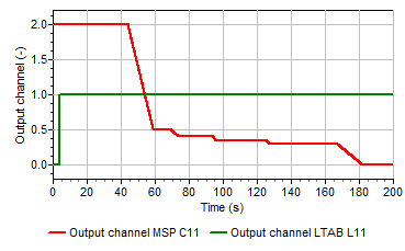
The above example is modified slightly. The real input value is still a constant value of 2, LTAB becomes true at t = 4 s but at t= 100 s it becomes false. At t=100 s, the output value gets again the value of the real input (here CON = 2, for a time series this would be the actual value at t = 100 s). At t=120 s, LTAB becomes true again. As CON =2 is larger than the value for End point 1 (0.5), output of MSP is then again according to the prescribed control including an initial freeze period of 40 seconds..
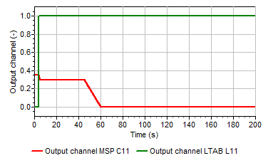
In the third sub-example, CON is set to 0.35. LTAB becomes true after 4 s. The MSP control identifies the correct position in the pattern (example; between End Point 3 and End Point 4). The MSP starts in the middle of Ramp 4 and continues with Freeze 5 until End point 5.
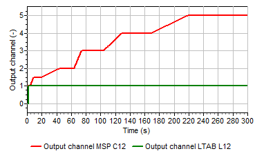
Examples
By changing the inputs of the MSP the signal can also increase in time towards the value of the last end point.