5.10. COND2
Purpose
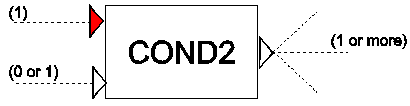
Compares the value from the first input channel with a set value. Furthermore, the comparison can be enabled/disabled depending on the logical condition of the second input channel.
Procedure
The (measured) value at the first input channel is compared with the set value. The type of comparison is chosen by the ‘Logical operator’. If the second input channel is TRUE, then the value of the condition is output. If the second output channel is FALSE, then the output is FALSE. Table 1 presents the possible scenarios for different input values.
Table 1: Possible scenarios
Scenario |
condition |
2nd input |
Output |
1 |
TRUE |
TRUE |
TRUE |
2 |
FALSE |
TRUE |
FALSE |
3 |
TRUE |
FALSE |
FALSE |
4 |
FALSE |
FALSE |
FALSE |
Parameters
Parameter |
input |
unit |
range |
default |
remarks |
|---|---|---|---|---|---|
Logical operator |
LT (less than)/ GT (greater than)/ LE (less equal)/ GE (greater equal)/ EQ (equal)/ NE (not equal) |
||||
Set value |
real |
||||
Reset time (true) |
real |
[s] |
0 |
||
Reset time (false) |
real |
[s] |
0 |
Remarks
If no logical signal line is attached to the second input channel it will default to TRUE and hence the COND2 will act identical to COND.
Examples
The example of COND is extended with the logical table LTAB to enable/disable the second (logical) input channel of COND2.
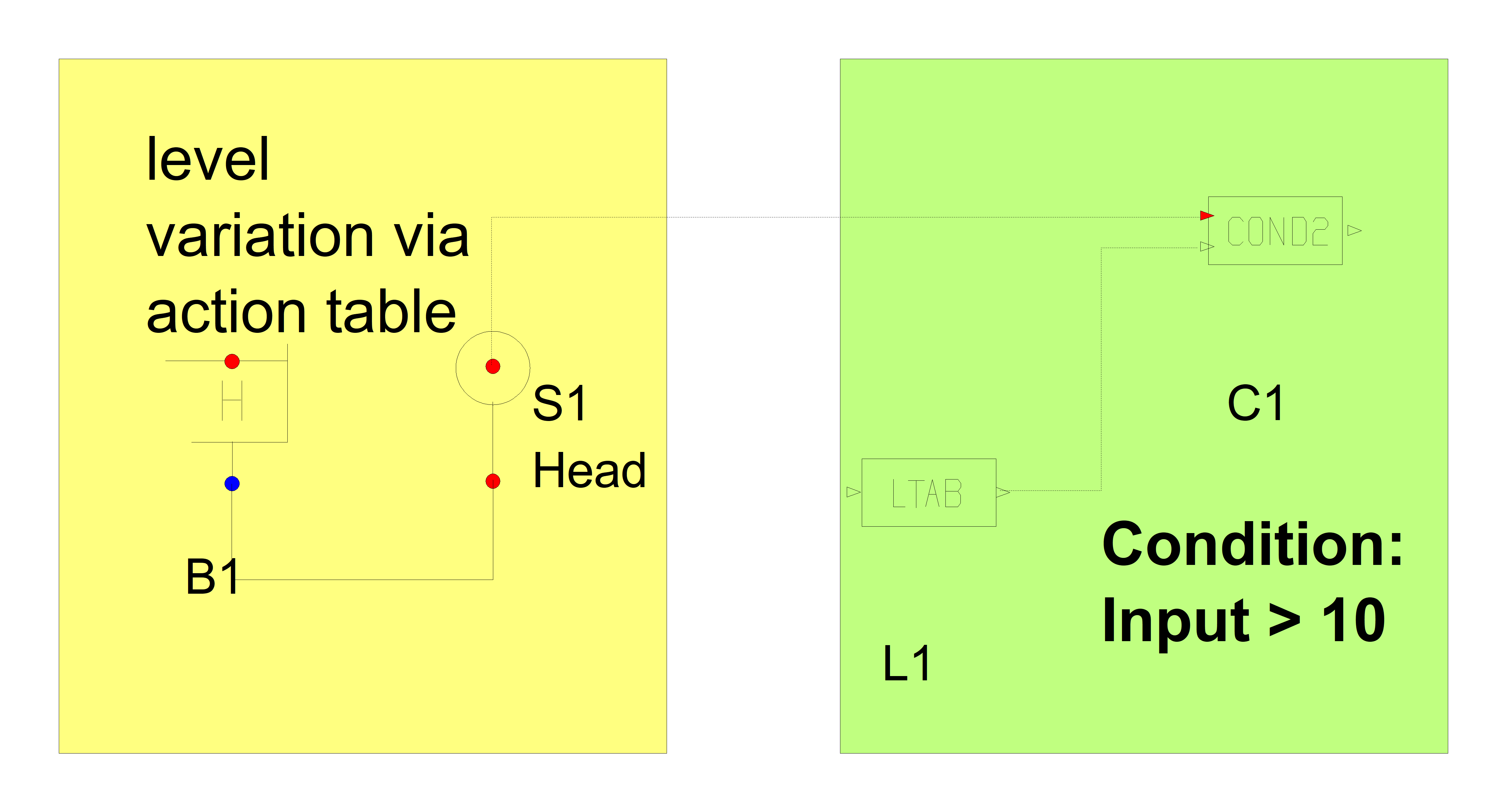
Fig 1: Control scheme
The input of LTAB is:
Time |
On(1) Off(0) |
|---|---|
(-) |
|
0 |
0 |
8.000 |
1.000 |
14.00 |
0 |
16.00 |
1.000 |
Figures Fig. 5.10.1 and Fig. 5.10.2 show the output when both ‘reset times’ are not used (0 seconds).
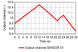
Fig. 5.10.1 variation of Head measured by Sensor
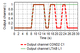
Fig. 5.10.2 Output of COND and LTAB