5.33. PID_N
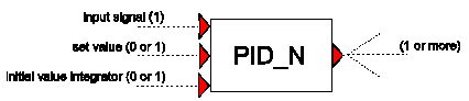
Purpose
To achieve a certain set value by adjusting a controlled variable of a hydraulic component, based on the difference between the input value and the set value. The PID_N component is similar to the PID component, except that the error can be normalized, as well as the output .
Procedure
The Proportional, Integrate, Differentiate Normalized (PID_N) component computes for each sample period Δt the error ε between an input signal x[n] and a set value xset:
(5.33.1)¶\[\varepsilon\left\lbrack n \right\rbrack = x\left\lbrack n \right\rbrack - x_{\text{set}}\]
|
where n denotes the present sample. This error is then normalized by the input lower bound and upper bound values: |
(5.33.2)¶\[\varepsilon^{'} = \frac{\varepsilon}{x_{\text{upper}} - x_{\text{lower}}}\]
|
The unscaled output signal is computed by |
Proportioning: |
(5.33.3)¶\[y_{p}^{'}\left\lbrack n \right\rbrack = c_{p}\varepsilon^{'}\left\lbrack n \right\rbrack\]
|
Integrating: |
(5.33.4)¶\[y_{i}^{'}\left\lbrack n \right\rbrack = y_{i}^{'}\left\lbrack n - 1 \right\rbrack + \frac{c_{p}}{c_{i}}\varepsilon^{'}\left\lbrack n \right\rbrack\text{Δt}\]
|
or Differentiating the normalized error: |
(5.33.5)¶\[y_{d}^{'}\left\lbrack n \right\rbrack = c_{p}c_{d}\frac{\varepsilon^{'}\left\lbrack n \right\rbrack - \varepsilon^{'}\left\lbrack n - 1 \right\rbrack}{\text{Δt}}\]
|
where cp is the “gain”, ci is the “integration time constant”, cd is the “differentiation time constant”, Δt is the sample time-step and [n-1] denotes the previous sample. The equations above can be combined to give an unscaled output signal, which is either: |
Proportional (P): |
(5.33.6)¶\[y^{'} = y_{p}^{'} + c_{0}\]
|
Proportional and Integrated (PI): |
(5.33.7)¶\[y^{'} = y_{p}^{'} + y_{i}^{'}\]
|
or Proportional, Integrated and Differentiated (PID): |
(5.33.8)¶\[y^{'} = y_{p}^{'} + y_{i}^{'} + y_{d}^{'}\]
|
where c0 is an offset value. Finally, the scaled output signal is obtained using the output lower bound and upper bound values: |
(5.33.9)¶\[y = y^{'}\left( y_{\text{upper}} - y_{\text{lower}} \right) + y_{\text{lower}}\]
|
Parameters
Parameter |
input |
unit |
range |
default |
remarks |
|---|---|---|---|---|---|
Initial setpoint |
real |
Can be overruled by 2nd input channel |
|||
Lower bound (input) |
real |
||||
Upper bound (input) |
real |
||||
Accuracy of recorded value |
real |
See remarks |
|||
Sample time interval |
real |
[s] |
See remarks |
||
Type of control |
P/ PI/ PID |
||||
Gain |
real |
||||
Integration time constant |
real |
[s] |
|||
Differentiation time constant |
real |
[s] |
|||
Offset value (bias) |
real |
only if ‘Type of Control” = P |
|||
Initial value of integrator |
real |
only if ‘Type of Control” = PI or PID Can be overruled by 3rd input channel |
|||
Lower bound |
real |
||||
Upper bound |
real |
||||
Ramp value CTRL_UP |
real |
max. positive change per second |
|||
Ramp value CTRL_DOWN |
real |
max. negative change per second |
Remarks
The Sample time interval is used to decrease the resolution of the input signal. A PLC-controller can have a different sample time than the simulation time.
If the difference between the measured (recorded) value and setpoint is smaller than the accuracy, the error is set to zero.
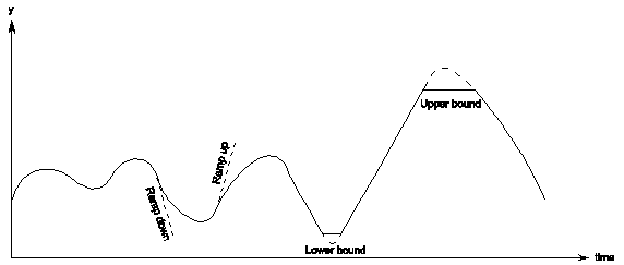
The PID component allows an ‘upper bound’ and a ‘lower bound’ to be imposed on the output signal.
When the output value “hits” the upper or lower bound the control system can not follow the error anymore and has no possibility to feed back to the system. If this situation remains long enough the integrator fills with a large value, which inhibits timely reaction if the error value changes direction (sign). To prevent this, a simple anti-reset windup provision is implemented. This provision suspends the accumulating of the error during the time that the output value violates the lower or upper bound.
Furthermore, a maximum allowable ‘ramp value’ can also be specified to control the rate of change of the output.
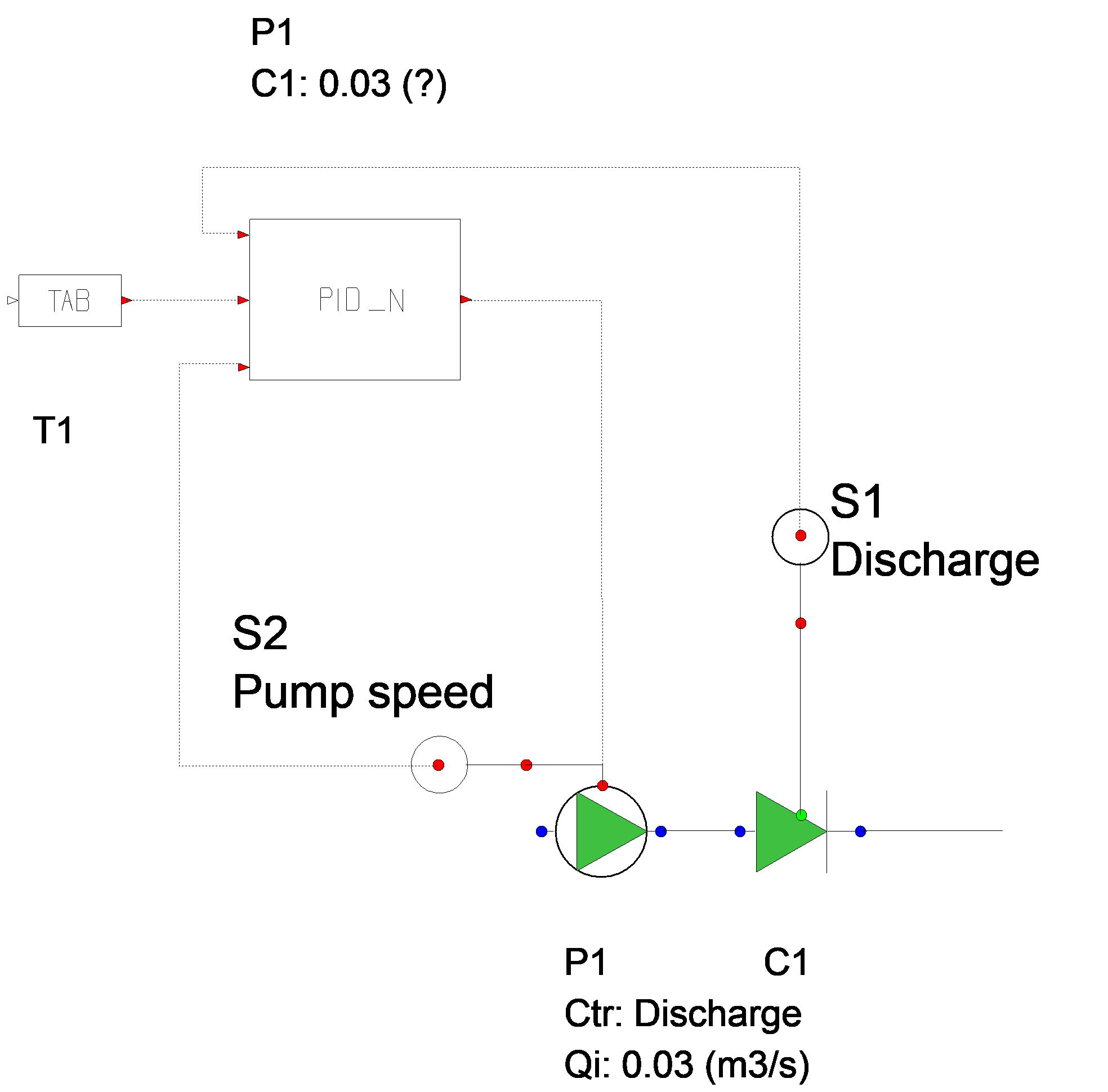
The integrating part can be initialised with a non-zero value. This can be used to adjust the PID controller to the hydraulic steady state (see examples).
In the steady state, the error should be equal to zero. This ensures that the entire system is in a true steady state.
|
Figure 5: PID operation |
It is the user’s responsibility to choose, and so that the output signal can be used by the controlled hydraulic component. For instance, if a valve is the controlled hydraulic component then the PID output signal must have a lower bound of 0 and an upper bound of 1.
Component Messages
Message |
Explanation |
|---|---|
Integrator must be less than upper bound |
Input validation |
Integrator must be greater than lower bound |
Input validation |
Offset must be less than upper bound |
Input validation |
Offset must be greater than lower bound |
Input validation |
Discrepancy with setpoint value and measured value |
|
ERROR: Discrepancy with setpoint value more than 25 % |
The control system and hydraulic system must be in equilibrium for the steady state, see remarks |
Target below lowerbound, anti-reset windup provision activated |
Informative |
Target above lowerbound, anti-reset windup prov. de-activated |
Informative |
Target above upperbound, anti-reset windup provision activated |
Informative |
Target below upperbound, anti-reset windup prov. de-activated |
Informative |
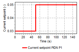
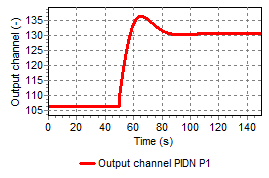
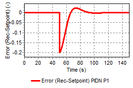
Examples
|
|
|