5.37. RAMP
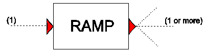
Purpose
To limit the rate of change of the input signal (value per second). This component can for instance be used to limit the rate of opening or closing a valve
Procedure
The input signal is limited to a maximum rate of change. Different rates are allowed for increases and decreases in the input signal.
Parameters
Parameter |
input |
unit |
range |
default |
remarks |
|---|---|---|---|---|---|
Ramp increase |
real |
||||
Ramp decrease |
real |
Remarks
None.
Examples
Figure 1 presents the input and output signals for a ramp component. The thin green line represents the input signal, while the thick red line represents the output signal. The input signal is a block function. The used ‘ramp increase’ parameter is 1, that means that the maximum change per second is 1 and it takes 10 seconds to reach the required input value. The used ‘Ramp decrease’ parameter is 2; so it takes 5 seconds to change from 10 to 0.
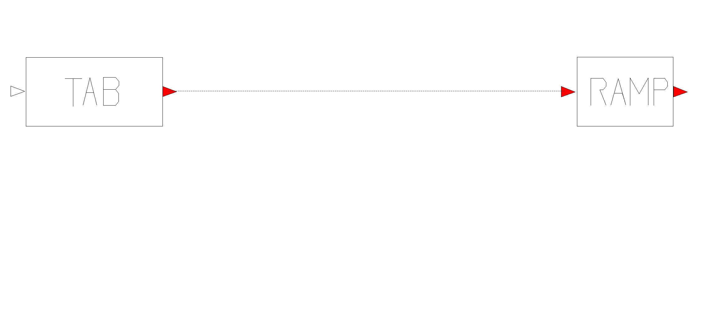
Fig. 5.37.1 Input and output signals for RAMP (incr = 1, decr = 2)
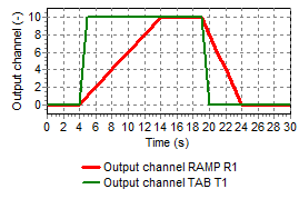
Fig. 5.37.2 Input and output signals for RAMP (incr = 1, decr = 2)