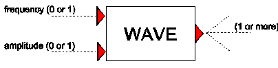
5.50. WAVE
Purpose
Generates a periodic, time dependent signal.
Procedure
The WAVE component can produce Sine, Square and Sawtooth signals:
The signal is defined by an amplitude, period (=1/frequency) and bias as explained in figure 1.
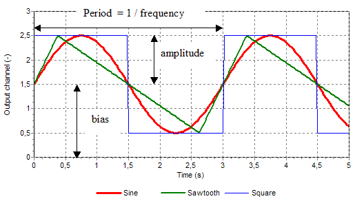
Fig. 5.50.1 the three different wave types and input definitions
The start of the wave is defined by the so-called initial phase fraction. This phase is a fraction of a period. In figure 2 the wave signals of sine, sawtooth and square have an initial phase fraction of respectively 0.25, 0.5 and 0.75.
For the Sine signal next equation is used:
in which:
a = amplitude (-)
b = frequency multiplier (-)
f = frequency (Hz)
t = time (s)
c = initial phase fraction (-)
d = bias (-)
The frequency and amplitude are input parameters but they can be overruled by the signal lines connected to the input channels.
Using the frequency input channel the ratio between the specified frequency and amplitude parameters can be maintained (Freq dependent amplitude = True) during the simulation.
To prevent start-up phenomena the amplitude can be increased from 0 to its full value within a specified start-up time.
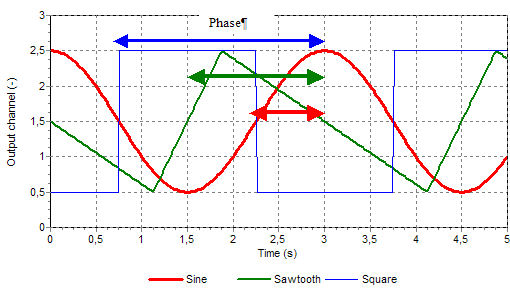
Fig. 5.50.2 Begin point of wave is defined by the initial phase fraction
Parameters
Parameter |
input |
unit |
range |
default |
remarks |
|---|---|---|---|---|---|
Waveform |
Sine/ Square/ Sawtooth |
||||
Frequency dependent amplitude |
Boolean |
YES/ NO |
Ignored if a signal is connected to the amplitude channel |
||
Initial frequency |
real |
Hz |
|||
Initial amplitude |
real |
[-] |
|||
Initial phase fraction |
real |
[-] |
[0,1] |
0 |
defines begin of wave; part of period shifted to left |
Rising phase fraction |
real |
[-] |
[0,1] |
If type = Sawtooth: Fraction of sawtooth period for rising part |
|
Frequency multiplier |
real |
[-] |
[1e-8, 1e8] |
1 |
|
Wave bias |
real |
0 |
|||
Start-up time |
real |
[s] |
[0, 1e8] |
0 |
Messages
Message |
Type |
Remarks |
|---|---|---|
Timestep too large for Period (1/freq) |
Warning |
Required time step less than 1/10 of period |
Period (1/freq) must be at least 2 * dt |
Error |
Frequency and time step do not match; use smaller time step |
Remarks
An application for the frequency multiplier are pump induced vibrations. These vibrations depends on the number of blades but the main frequency is defined by the pump speed which is connected to the frequency channel. The frequency multiplier is the number of blades.
Examples
The input parameters of the three waves signals of Figure 1 are:
Initial frequency |
0.33 (Hz) |
Initial amplitude |
1 (-) |
Initial phase fraction |
0.0 (-) |
Frequency multiplier |
1 (-) |
Wave bias |
1.5 (-) |
Start-up time |
0 (s) |
In figures 3 – 7 some combinations of two sine waves are shown. The input parameters of the basic sine wave are listed below:
Initial frequency |
1 (Hz) |
Initial amplitude |
1 (-) |
Initial phase fraction |
0.0 (-) |
Frequency multiplier |
1 (-) |
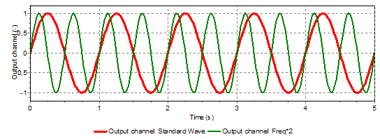
Fig. 5.50.3 Different initial frequencies (1 and 2 Hz)
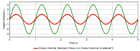
Fig. 5.50.4 Different initial amplitudes (1 and 3)
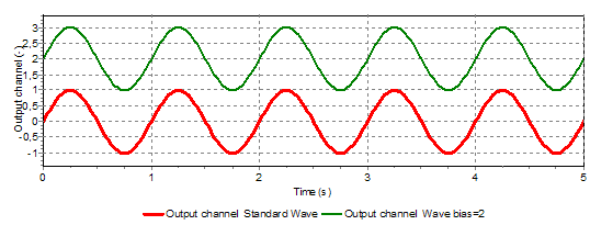
Fig. 5.50.5 Different wave bias (0.0 and 2.0)
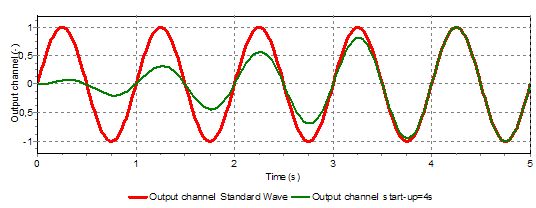
Fig. 5.50.6 Sine waves with and without start-up times (0.0 and 4.0)
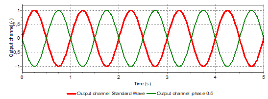
Fig. 5.50.7 Different initial phases (0.0 and 0.5)