5.4. 2COND
Purpose
Compares the results of two conditions (2COND).
Procedure
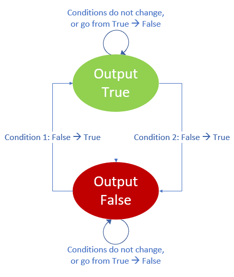
Each input channel value is compared with its corresponding set value. The type of comparison is chosen by the ‘Logical operator’. Condition 1 is evaluated with the first (upper) input channel value. Condition 2 is evaluated with the second (lower) input channel value. If condition 1 becomes true, the output value is set to true; if condition 2 becomes true, the output value becomes false. Diagram 1 presents the state diagram.
Diagram 1: State diagram of the output
Parameters
Parameter |
input |
unit |
range |
default |
remarks |
|---|---|---|---|---|---|
Logical operator C1 |
LT (less than)/ GT (greater than)/ LE (less equal)/ GE (greater equal)/ EQ (equal)/ NE (not equal) |
||||
set value C1 |
real |
||||
reset time C1 |
real |
[s] |
0 |
||
Logical operator C2 |
LT (less than)/ GT (greater than)/ LE (less equal)/ GE (greater equal)/ EQ (equal)/ NE (not equal) |
||||
set value C2 |
real |
||||
reset time C2 |
real |
[s] |
0 |
||
Initial status |
TRUE/ FALSE |
Remarks
Both conditions must hold for periods longer than their corresponding ‘reset time’ before the output will switch its original value. If both conditions do not hold for periods longer than their ‘reset time’ then the output will keep its original value and the timing periods will be restarted.
If both transitions would occur within one time step, the behaviour is such that the output will be True. In other words, Condition 1 has priority over Condition 2.
Examples
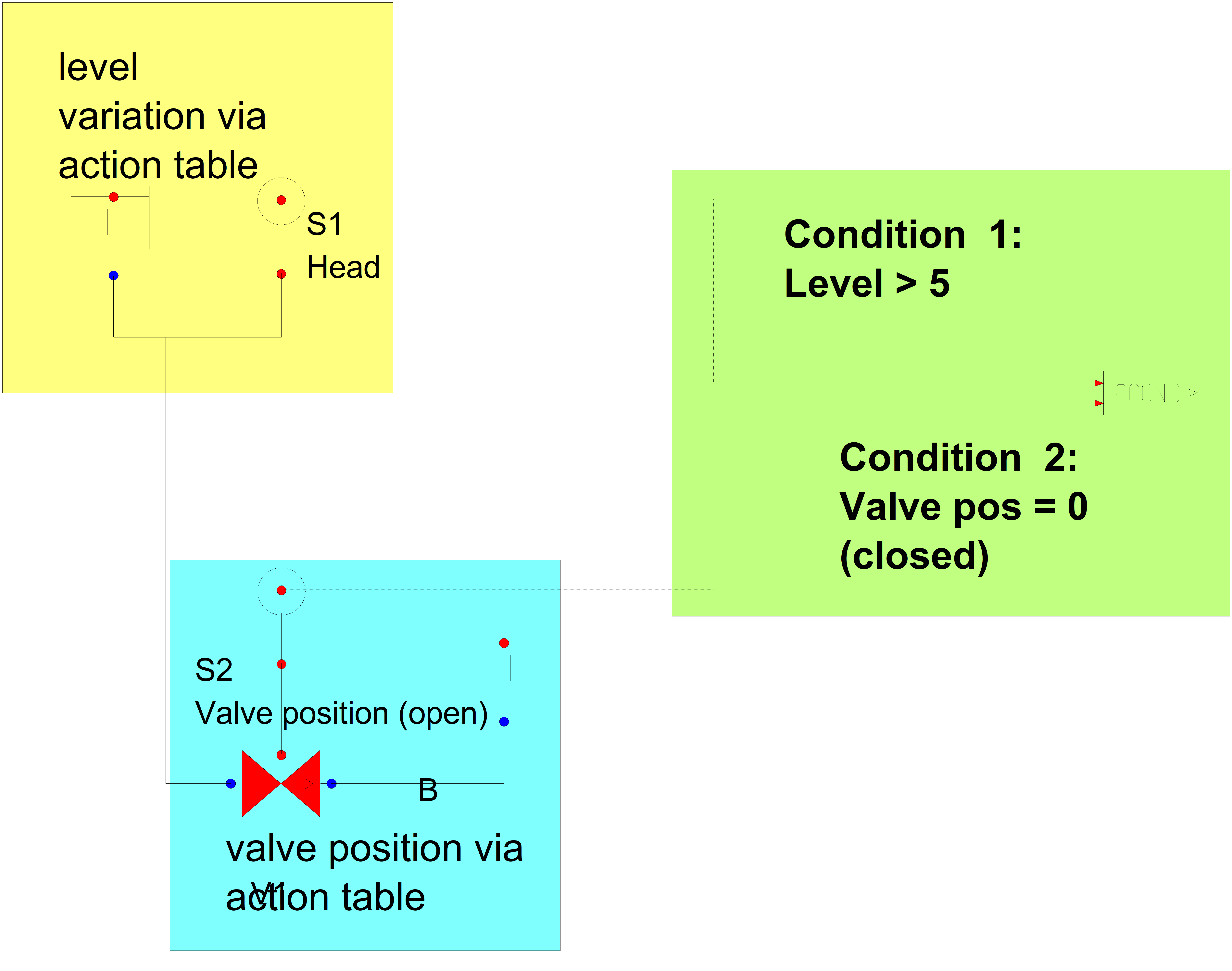
Fig 1: Control scheme
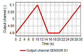
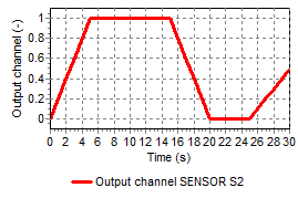
The input signals of 2COND are gathered from a prescribed Head and valve position and shown in figure 2a and 2b.
|
|
Fig 2a: prescribed head |
Fig 2b: prescribed valve position |
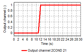
The initial state of 2COND is set to false, because the level (condition 1) is below 5 m. The behaviour of 2COND with both reset times 0 s, is shown in figure 3a.
Introducing a reset time of 6 s for both condition gives a rather different behaviour shown in figure 3b.
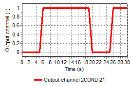 Fig 3a: Output 2COND with both reset times 0 s
|
|