6.6. Heat air vessel

Fig. 6.6.1 Schematic overview of a heat air vessel
Supplier type
Type label |
Description |
Active |
|---|---|---|
Heat Airvessel |
Vertically positioned, prismatic (constant area), non-vented, isolated air vessel |
No |
6.6.1. Mathematical models
A vertical air vessel or air chamber without air inlet can be modelled by four equations. The first equation describes the behaviour of the enclosed air:
with:
Variable |
Description |
Units |
|---|---|---|
P |
absolute air pressure |
N/m2 |
V |
air volume |
m3 |
k |
Laplace coefficient |
- |
C |
constant |
Nm if k = 1 |
The Laplace coefficient depends on the thermodynamic behaviour of the air. Isothermal expansion is described by k = 1. Adiabatic expansion is described by k = 1.4.
The second equation governs the discharge Q (defined positive, when the flow is from the air vessel into the system) :
in which Aav denotes the storage surface and xf the fluid level in the air chamber with respect to the global co-ordinate system. The minus sign indicates that the chamber supplies fluid to the system when the fluid level is decreasing in time.
In steady state the air vessel does not supply fluid. Hence in steady state the governing equation is:
The last equation (6.6.4) defines the temperature of the water in the air vessel. This air vessel model assumes that the vessel is thermally isolated, i.e. no heat is transferred to or from the outside world. The water in the air vessel is assumed to be mixed instantaneously (ideally mixed tank). Using an energy balance for the air vessel, the change of temperature can be expressed as a function of the energy inflow:
During outflow the temperature in the air vessel does not change, the outflow temperature is taken equal to the temperature in the air vessel.
6.6.2. Airvessel properties
6.6.2.1. Hydraulic specifications
Description |
Input |
SI-units |
Remarks |
|---|---|---|---|
Bottom level |
real |
[m] |
See remarks |
Top level |
real |
[m] |
See remarks |
Air quantity by |
Fluid Level Air volume Constant C |
See remarks |
|
Initial fluid level |
real |
[m] |
If ”air quantity by” = Fluid Level |
Initial air volume |
real |
[m³] |
If ”air quantity by” = Air volume |
Initial C in P*V = C |
real |
[J] |
If “air quantity by” = Constant C |
Chamber area |
real |
[m2] |
|
Laplace coefficient |
real |
[-] |
|
Temperature at t = 0 [s] |
real |
[°C] |
Remarks
The air volume and the fluid level in the airvessel are determined by either the initial fluid level, the initial air volume or the initial constant C. One quantity has to be given by the user, the other two quantities are calculated by Wanda.
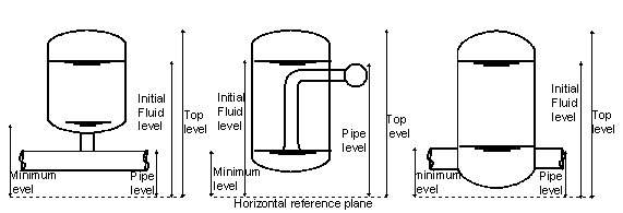
Fig. 6.6.2 Modelling assumptions per heat air vessel type.
An airvessel in WANDA is modelled with a straight instead of a rounded top and bottom. The volume of the real airvessel and the WANDA airvessel should be the same. The top and bottom level should therefore be taken respectively lower and higher than the level of the real airvessel. How much lower and higher depends on the shape of the real airvessel.
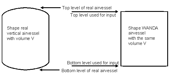
Fig. 6.6.3 Modeled heat air vessel versus real heat air vessel
Meaning of Pressure in property window Airvessel:
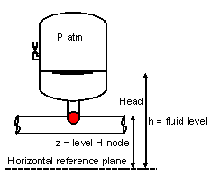
Fig. 6.6.4 Variables required for a heat air vessel
Variable |
Description |
Units |
|---|---|---|
Head |
Head in node of airvessel |
m |
Pressure P (in node) |
\(\rho_l g (H - z)\) relative to the atmosphere |
Pa |
z |
Height specified by a particular node |
m |
Air pressure (absolute) |
\(\rho_a g (H-h) + P_{atm}\) |
Pa |
h |
Fluid level |
m |
6.6.2.2. Component specific output
Fluid level [m]
Air pressure (absolute) [N/m2.abs]
Air volume [m3]
Tank temperature [°C]
6.6.2.3. Component messages
Message |
Type |
Explanation |
|---|---|---|
Top level below bottom level |
Error |
This is in input error by the user |
Initial fluid level not in between top and bottom level of air chamber |
Error |
This is in input error by the user |
Specified air volume larger than vessel volume |
Error |
This is in input error by the user |
Empty airchamber |
Warning |
Computation can continue, since storage area is constant independent of the height. The results will not be physically correct, but may help the design of the air vessel. |
Airchamber refilled |
Info |
There has been a time with completely emptied air chamber, above. |