6.2. Heat nodes
A Heat node connects two or more Heat components with each other. This Heat node is represented by a connection line in the diagram and is connected to the hydraulic connect point of a Heat component (orange dot). For more information about the connection line, see connecting_components.
Heat node type
Table 6.2.1 summerizes the different type of Heat nodes.
Type label |
Description |
|
|---|---|---|
Heat node |
Default Heat node for connecting components in WANDA Heat |
|
Heat node init pT |
Heat node defining initial pressure and temperature |
|
Heat node init p |
Heat node defining initial pressure |
|
Heat node init T |
Heat node defining initial temperature |
|
Heat node with demand |
Heat node with base-demand and pattern (for use in drinking water networks) |
|
Heat node conditional init pT |
heat node with conditional initial pressure and temperature. WANDA only defines the temperature and pressure in the node when it is not defined by the system |
|
6.2.1. Mathematical model
Temperature calculation for Heat node
The specific internal energy in the Heat node is calculated based on an energy balance. The energy balance takes all energy flows connected to the Heat node into account. For n components the equation is as follows:
with:
Variable |
Description |
Units |
|---|---|---|
u |
Specific internal energy |
J/kg |
\(\dot{m}\) |
mass flow |
kg/s |
The specific internal energy of the Heat node itself is defined by setting the specific internal energy of the outflow (flow away from the Heat node) equal to the specific internal energy of the Heat node itself. The Temperature is derived from this result. At the end this means that the temperature in the Heat node is modeled as completely mixed.
Cavitation in Heat node
If the pressure drops below the vapour pressure, cavitation occur. Cavitation in a Heat node is only taken into account if the Heat node is connected to a PIPE.
Default output properties
Each type of Heat node has a few standard output properties. These are:
Output properties |
Units |
|---|---|
Pressure |
N/m2 |
Temperature |
°C |
Total Pressure |
N/m2 |
Void fraction (cavitation) |
- |
6.2.2. Heat node
A Heat node is the standard hydraulic node for WANDA Heat, by default generated after connecting two Heat components.
The output can be calculated if the Heat node is part of a fully connected (“open”) hydraulic network with one or more boundary conditions for the pressure and one or more boundary conditions for the temperature (use of BOUNDPT, BOUNDMT or BOUNDT(PM) ). “Open” means that each Heat component has a certain relation between pressure and mass flow and that there is at least one component prescribing the pressure (e.g. no fully closed valves).
Input properties
Description |
Input |
SI-units |
Remarks |
|---|---|---|---|
Elevation |
real |
[m] |
Messages
Message |
Message |
Explanation |
|---|---|---|
Cavitation in steady state not allowed |
error |
The lowest pressure in the Heat node is less than the vapour pressure |
Pressure < Pvapour; Cavitation not supported for node without PIPE connections |
warning |
In this Heat node there is no PIPE component connected. The cavitation model needs at least 1 PIPE to compute the vapour volume. This warning is only given the first time the pressure condition is true; the rest of the simulation is physically invalid. |
Cavitates |
informative |
Heat node starts cavitating; the lowest pressure drops below the vapour pressure |
Cavitation collapses |
informative |
Void fraction becomes 0 |
Change Type to Heat node with initial pressure |
error |
Heat node is part of an isolated part of the network in which no information is available for the pressure; the user must define the pressure in this part of the model. |
Change Type to Heat node with initial temperature |
error |
Heat node is either part of an isolated part of the network in which no information is available for the temperature or there is no flow in the connected components; the user must define the temperature in this part of the model. |
6.2.3. Heat node init (initial) pT
If the Heat node is part of a “closed” or ”isolated” hydraulic network, there is no connection with a boundary condition like a BOUNDPT, then the actual pressure and temperature in the steady state computation cannot be determined.
This is explained in Fig. 6.2.1: the pressure and temperature in the nodes Node1 and Node2 cannot be calculated.
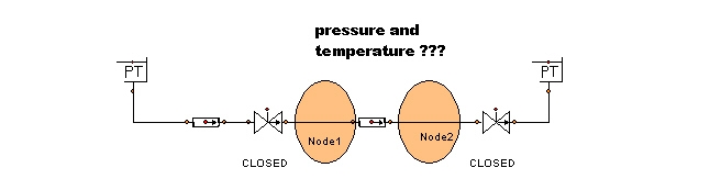
Fig. 6.2.1 Example of an isolated hydraulic network without a boundary condition.
It is therefore necessary to define the pressure and temperature for this area in one of the Heat nodes. It is up to the user which Heat node the pressure will be prescribed (changed into the type: Heat node init pT). The type of the node can be changed via the property window (drop down list in “Type” field).
Note: the initial pressure and temperature are only applied during steady state. If during transient an “isolated network” occurs the pressure and temperature of the previous time step will be used.
Note: By using the node with initial pressure, the mass flow at the node is no longer set to zero. This can thus result in a non-zero mass flow from the node. A warning is issued when this occurs.
Input properties
Description |
Input |
SI-units |
Remarks |
|---|---|---|---|
Elevation |
real |
[m] |
|
Pressure t=0 |
real |
[N/m²] |
|
Temperature t=0 |
real |
[°C] |
Messages
Message |
Message |
Explanation |
|---|---|---|
Cavitation in steady state not allowed |
error |
The lowest pressure in the Heat node is less than the vapour pressure |
Pressure < Pvapour; Cavitation not supported for Heat node without PIPE connections |
warning |
In this Heat-node there is no PIPE component connected. The cavitation model needs at least 1 PIPE to compute the vapour volume. This warning is only given the first time the pressure condition is true; the rest of the simulation is physically invalid. |
Cavitates |
informative |
Heat node starts cavitating; the lowest pressure drops below the vapour pressure |
Cavitation collapses |
informative |
Void fraction becomes 0 |
Mass continuity not observed |
Warning |
The core quantity mass flow of the node is not zero, meaning the model is “leaking” flow in the node |
6.2.4. Heat node init (initial) p
As with the “Heat node init pT” above, the “Heat node init p” can be used in an isolated part of the model to initiate the pressure in the H-node. Or when there is no flow in this part of the system. When using this H-node, there should be another component or H-node which defines the temperature.
The initial pressure is only applied during steady state. If during transient an “isolated network” occurs the pressure and temperature of the previous time step will be used.
Note: By using the node with initial pressure, the mass flow at the node is no longer set to zero. This can thus result in a non-zero mass flow from the node. A warning is issued when this occurs.
Input properties
Description |
Input |
SI-units |
Remarks |
|---|---|---|---|
Elevation |
real |
[m] |
|
Pressure t=0 |
real |
[N/m²] |
Messages
Message |
Message |
Explanation |
|---|---|---|
Cavitation in steady state not allowed |
error |
The lowest pressure in the Heat node is less than the vapour pressure |
Pressure < Pvapour; Cavitation not supported for H-node without PIPE connections |
warning |
In this Heat node there is no PIPE component connected. The cavitation model needs at least 1 PIPE to compute the vapour volume. This warning is only given the first time the pressure condition is true; the rest of the simulation is physically invalid. |
Cavitates |
informative |
Heat node starts cavitating; the lowest pressure drops below the vapour pressure |
Cavitation collapses |
informative |
Void fraction becomes 0 |
Mass continuity not observed |
Warning |
The core quantity mass flow of the node is not zero |
Change Type to Heat node with initial temperature |
error |
Heat node is either part of an isolated part of the network in which no information is available for the temperature or there is no flow in the connected components; the user must define the temperature in this part of the model. |
6.2.5. Heat node init (initial) T
As with the “Heat node init pT” above, the “Heat node init T” can be used in an isolated part of the model to initiate the temperature in the Heat node. When using this Heat node, there should be another component or Heat node which defines the pressure.
The initial temperature is only applied during steady state and only if there are no connected components which already specify the temperature. In transient the value of the former time step is used.
Input properties
Description |
Input |
SI-units |
Remarks |
|---|---|---|---|
Elevation |
real |
[m] |
|
Temperature t = 0 [s] |
real |
[°C] |
Messages
Message |
Message |
Explanation |
|---|---|---|
Cavitation in steady state not allowed |
error |
The lowest pressure in the H-node is less than the vapour pressure |
Pressure < Pvapour; Cavitation not supported for H-node without PIPE connections |
warning |
In this H-node there is no PIPE component connected. The cavitation model needs at least 1 PIPE to compute the vapour volume. This warning is only given the first time the pressure condition is true; the rest of the simulation is physically invalid. |
Cavitates |
informative |
H-node starts cavitating; the lowest pressure drops below the vapour pressure |
Cavitation collapses |
informative |
Void fraction becomes 0 |
Change Type to Heat node with initial pressure |
error |
Heat node is part of an isolated part of the network in which no information is available for the pressure; the user must define the pressure in this part of the model. |
6.2.6. Heat node with demand
This Heat node will subtract a demand volume flow from the network. This Heat node is very useful for modelling drinking water distribution networks over a longer period of time and the application is comparable to the EPANET approach.
With this heat node the volumetric base demand can be specified as the discharge to end-users connected to this node. The pattern can be used to vary the actual (instantaneous) discharge over time (e.g. high peaks during morning and evening but low at night). The pattern will be repeated if the simulation time is larger than the table period.
Input properties
Description |
Input |
SI-units |
Remarks |
|---|---|---|---|
Elevation |
real |
[m] |
|
Base demand |
real |
[m³/s] |
|
Pattern |
None Table |
||
Pattern table |
table |
If Pattern = Table Multiplication factor applied to base pattern |
Specific output properties
Node specific output for this Heat node is:
Demand [m³/s]
Volume delivered [m³]
Messages
Message |
Message |
Explanation |
|---|---|---|
Cavitation not allowed |
Error |
Cavitation is not possible for the Heat node with demand. |
6.2.7. Heat node conditional init pT
If the Heat node is part of a “closed” or ”isolated” hydraulic network, there is no connection with a boundary condition like a BOUNDPT, then the actual pressure and temperature in the steady state computation cannot be determined.
In Fig. 6.2.2 the pressure and temperature in the nodes Node1 and Node2 cannot be calculated.
Fig. 6.2.2 Closed hydraulic network where the temperature cannot be calculated.
It is therefore necessary to define the pressure and temperature for this area in one of the Heat nodes. It is up to the user which Heat node the pressure will be prescribed. The type of the node can be changed via the property window (drop down list in “Type” field). However when using for example the parameter script is can be useful that the node only describes the pressure and temperature when they are part of an isolated system. For this purpose the conditional init PT node can be used. This node only pre describes its pressure or temperature when it is part of an isolated system.
Note: the initial pressure and temperature are only applied during steady state. If during transient an “isolated network” occurs the pressure and temperature of the previous time step will be used.
Note: By using the node with initial pressure, the mass flow at the node is no longer set to zero. This can thus result in a non-zero mass flow from the node. A warning is issued when this occurs.
Input properties
Description |
Input |
SI-units |
Remarks |
|---|---|---|---|
Elevation |
real |
[m] |
|
Pressure t=0 |
real |
[N/m²] |
|
Temperature t=0 |
real |
[°C] |
Messages
Message |
Message |
Explanation |
|---|---|---|
Cavitation in steady state not allowed |
error |
The lowest pressure in the Heat node is less than the vapour pressure |
Pressure < Pvapour; Cavitation not supported for Heat node without PIPE connections |
warning |
In this Heat-node there is no PIPE component connected. The cavitation model needs at least 1 PIPE to compute the vapour volume. This warning is only given the first time the pressure condition is true; the rest of the simulation is physically invalid. |
Cavitates |
informative |
Heat node starts cavitating; the lowest pressure drops below the vapour pressure |
Cavitation collapses |
informative |
Void fraction becomes 0 |
Mass continuity not observed |
Warning |
The core quantity mass flow of the node is not zero, meaning the model is “leaking” flow in the node |