6.9. Heat exchanger
Fall type
Type label |
Symbol |
Description |
Active |
|---|---|---|---|
|
Supply heat to or extract heat from the fluid by directly specifying a heat input |
Yes |
|
|
Supply heat or extract heat to the fluid by specifying a temperature at downstream Heat node |
Yes |
|
|
Supply heat to or extract heat from the fluid by directly specifying a heat input, with user specified limits for the minimum and maximum temperatures |
Yes |
|
|
Exchange heat with surroundings due to temperature difference between fluid and ambient temperature. |
Yes |
|
|
Heat demand for district heating systems with different time scales for heating and warm (tap) water. |
Yes |
|
|
Supply heat to the fluid by gas combustion |
Yes |
|
|
Heat supply via a solar collector |
Yes |
|
|
Heat supply via a solar collector based on ISO 9806:2017 |
Yes |

6.9.1. Heat supply QHeat in
The heat supply is used to supply a constant heat flux to the system. The user sets the amount of heat supplied (+) or extracted (-). Wanda calculates how much the fluid heats or cools down as a result. Next to this, the hydraulic losses are also included via a loss coefficient. This hydraulic loss can be converted to heat by the fraction-generated heat to fluid.
6.9.1.1. Mathematical model
The head loss (definition based on liquid domain) is given by:
with:
variable |
Description |
Units |
|---|---|---|
\(\Delta H\) |
Head loss |
m |
C |
the loss coefficient |
s2/m5 |
Q |
the flow rate |
m3/s |
This can be rewritten in terms of a pressure drop and mass flow as follows:
with:
variable |
Description |
Units |
|---|---|---|
\(\Delta p\) |
pressure drop |
N/m2 |
\(\rho\) |
density of the fluid at the upstream side |
kg/m3 |
\(g\) |
gravitational acceleration |
m/s2 |
\(\dot{m}\) |
mass flow rate |
kg/s |
\(\Delta z\) |
height difference between connection points |
m |
The temperature change is computed from:
with:
variable |
Description |
Units |
|---|---|---|
\(c_{p1}/c_{p2}\) |
specific head of the fluid |
J/kg/K |
\(T_{1}/T_{2}\) |
upstream/ downstream temperature |
K |
\(Q_{input}\) |
heat supplied to the system |
W |
\(Q_{gen}\) |
generated heat |
W |
\(fr\) |
Fraction of generated heat transferred to the fluid |
- |
The generate heat flux is given by:
The heat input is always supplied and therefore zero flow is not possible, since this would result in an infinite temperature. The heat supplied is calculated as:
6.9.1.2. Hydraulic specifications
Description |
Input |
SI-units |
remarks |
|---|---|---|---|
C-value dH=CQ^2 |
real |
[s2/m5] |
Q is fluid flow rate |
Fraction gen. heat to fluid |
real |
[-] |
Default = 0 |
Initial heat supply |
real |
[W] |
Can be controlled by action table |
6.9.1.3. Component specific output
Heat supplied [W]
Generated Heat flux [W]
6.9.1.4. Component messages
Message |
Type |
Explanation |
|---|---|---|
Zero flow not allowed |
Error |
Heat input with zero flow not possible, because that would require the temperature to become infinite. |
6.9.1.5. Actions
The action table (control connection) of this component controls the heat supply as function of time.
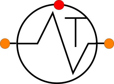
6.9.2. Heat supply Tdown
The heat supply Tdown is used to specify a fixed downstream temperature (constant or time-variable through action table). The amount of heat supplied (+) to or heat extracted (-) from the fluid is calculated by Wanda. The location of the downstream side is based on the actual flow direction (thus not based on the scheme definition).
6.9.2.1. Mathematical model
The head loss (definition based on liquid domain) is given by:
with:
variable |
Description |
Units |
|---|---|---|
\(\Delta H\) |
Head loss |
m |
\(C\) |
Loss coefficient |
s2/m5 |
\(Q\) |
Flow rate |
m3/s |
This can be rewritten in terms of a pressure drop and mass flow as follows:
with:
variable |
Description |
Units |
|---|---|---|
\(\Delta p\) |
pressure drop |
N/m2 |
\(\rho\) |
density of the fluid at the upstream side |
kg/m3 |
\(g\) |
gravitational acceleration |
m/s2 |
\(\dot{m}\) |
mass flow rate |
kg/s |
\(\Delta z\) |
height difference between connection points |
m |
The downstream temperature is set based on the user specified input. A change in flow direction will set the specified temperature at the opposite connection point.
The heat supplied is calculated from:
variable |
Description |
Units |
|---|---|---|
\(Q_s\) |
Heat supplied |
W |
\(c_{p1}/c_{p2}\) |
Upstream/downstream specific heat of the fluid |
J/kg/K |
\(T_1/T_2\) |
Upstream/downstream temperature of the fluid |
K |
The generate heat flux is given by:
6.9.2.2. Hydraulic specifications
Description |
Input |
SI-units |
remarks |
|---|---|---|---|
C-value (dH=CQ^2) |
real |
[s2/m5] |
Q is fluid flow rate |
Fraction gen. heat to fluid |
real |
[-] |
Default = 0 |
Initial downstr temp |
real |
[°C] |
Can be controlled by action table |
6.9.2.3. Component specific output
Heat supplied [W]
Generated Heat flux [W]
6.9.2.4. Component messages
None
6.9.2.5. Actions
The action table (control connection) of this component controls the downstream temperature as function of time.
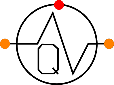
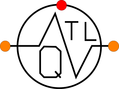
6.9.3. Heat supply QHeat with limits on T
The heat supply is used to supply a constant heat flux to the system. The user sets the amount of heat supplied (+) or extracted (-). Wanda calculates how much the fluid heats or cools down as a result, the downstream temperature is limited by user specified boundaries. The hydraulic losses are included via a loss coefficient. This hydraulic loss can be converted to heat by the fraction-generated heat to fluid.
6.9.3.1. Mathematical model
The head loss (definition based on liquid domain) is given by:
with:
variable |
Description |
Units |
|---|---|---|
\(Q\) |
Flow rate |
m3/s |
\(C\) |
Loss coefficient |
s2/m5 |
\(\Delta H\) |
Head loss |
m |
This can be rewritten in terms of a pressure drop and mass flow as follows:
with:
variable |
Description |
Units |
|---|---|---|
\(\Delta p\) |
pressure drop |
N/m2 |
\(\rho\) |
density of the fluid at the upstream side |
kg/m3 |
\(g\) |
gravitational acceleration |
m/s2 |
\(\dot{m}\) |
mass flow rate |
kg/s |
\(\Delta z\) |
height difference between connection points |
m |
The temperature change is computed from:
with:
variable |
Description |
Units |
|---|---|---|
\(c_{p1}/c_{p2}\) |
specific head of the fluid |
J/kg/K |
\(T_{1}/T_{2}\) |
upstream/ downstream temperature |
K |
\(Q_{input}\) |
heat supplied to the system |
W |
\(Q_{gen}\) |
generated heat |
W |
\(fr\) |
Fraction of generated heat transferred to the fluid |
- |
If the downstream temperature comes below or above the user specified extremes the temperature is set to this value, the user is informed by a message. The actual used heat flux is given as result. The generate heat flux is given by:
The heat supplied is calculated as:
6.9.3.2. Hydraulic specifications
Description |
Input |
SI-units |
remarks |
|---|---|---|---|
C-value (dH=CQ^2) |
real |
[s2/m5] |
Q is fluid flow rate |
Fraction gen. heat to fluid |
real |
[-] |
Default = 0 |
Minimum supply temperature |
Real |
[oC] |
|
Maximum supply temperature |
Real |
[oC] |
|
Initial heat supply |
real |
[W] |
Can be controlled by action table |
6.9.3.3. Component specific output
Heat supplied [W]
Generated Heat flux [W]
6.9.3.4. Component messages
Message |
Type |
Explanation |
|---|---|---|
Temperature set to upper bound |
Info |
This message is given once when the heat temperature is set to the upper bound |
Temperature set to lower bound |
info |
This message is given once when the heat temperature is set to the lower bound |
Temperature within bounds |
info |
This message is given when the temperature is again within bounds |
6.9.3.5. Actions
The action table (control connection) of this component controls the heat supply as function of time.
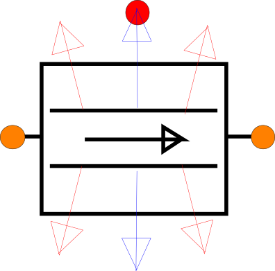
6.9.4. Heat exchanger
The heat exchanger component calculates in the transient state the heat transfer depending on the temperature difference between the ambient temperature and the fluid temperature using an integrated heat transfer coefficient.
Four different initial states are possible:
Heat exchanger
DownT and C- coef
DownT and Q supplied
DeltaT and Q supplied.
These are detailed in the Mathematical model.
6.9.4.1. Mathematical model
The head loss is defined as:
with:
variable |
Description |
Units |
|---|---|---|
\(Q\) |
Flow rate |
m3/s |
\(C\) |
Loss coefficient |
s2/m5 |
\(\Delta H\) |
Head loss |
m |
This can be rewritten in terms of a pressure drop and mass flow as follows:
with:
variable |
Description |
Units |
|---|---|---|
\(\Delta p\) |
pressure drop |
N/m2 |
\(\rho\) |
density of the fluid at the upstream side |
kg/m3 |
\(g\) |
gravitational acceleration |
m/s2 |
\(\dot{m}\) |
mass flow rate |
kg/s |
\(\Delta z\) |
height difference between connection points |
m |
The heat flow to (+) or from (-) the fluid is defined as:
with:
variable |
Description |
Units |
|---|---|---|
\(Q_{input}\) |
Heat supplied to the system |
W |
\(h\) |
Heat transfer coefficient |
W/K |
\(T_\infty\) |
External temperature (i.e., not influenced by the heat transfer) |
K |
\(T_f\) |
Fluid temperature |
K |
The energy equation is defined as:
The generate heat flux is given by:
The heat supplied is defined as:
Several options are available for the steady state computation (initial state). This setting defines how the steady state is calculated. Based on this initial state a constant heat transfer coefficient and/or a loss coefficient are calculated which is used throughout the transient computation.
- Heat ExchangerThe initial state is calculated based on a heat transfer coefficient input by the user.
- DownT and C-coeffInitial state is based on downstream temperature and a C-value. The downstream side is based on the initial flow direction and may differ from the scheme definition. The heat transfer coefficient is calculated as a result.
- DownT and QhsupInitial state is based on downstream temperature and a fixed heat supply. The downstream side is based on the initial flow direction and may differ from the scheme definition. The C-value and heat transfer coefficients are calculated as result of this initial steady state.
- DT and QhsupInitial state is based on a temperature difference (T1-T2) over the component and a fixed heat supply. The C-value and heat transfer coefficient are calculated as result of this initial steady state.
6.9.4.2. Hydraulic specifications
Description |
Input |
SI-units |
remarks |
|---|---|---|---|
Initial state |
Heat exchange DownT and C-coef DownT and Qhsup DT and Qhsup |
Only used for initial (steady state) calculation |
|
C-value (dH=CQ^2) |
real |
[s2/m5] |
Only if Initial state is: “Heat exchange” or “DownT and C-coef” |
Fraction gen. heat to fluid |
real |
[-] |
Default = 0 |
Heat transfer coefficient |
real |
[W/K] |
Only if Initial state is “Heat exchange” |
Initial heat supply |
real |
[kW] |
Only if Initial state is “DownT and Qhsup” or “DT and Qhsup” |
Initial downstr temp |
real |
[°C] |
Only if Initial state is “DownT and C-coef” or “DownT and Qhsup” |
Initial delta T |
real |
[°C] |
Only if Initial state is “DT and Qhsup” |
Initial ambient temperature |
real |
[°C] |
Can be controlled by action table |
6.9.4.3. Component specific output
Heat supplied [W]
Generated Heat flux [W]
Ambient temperature [°C]
6.9.4.4. Component messages
Message |
Type |
Explanation |
Unable to determine resistance and heat transfer coefficient: zero flow |
Error |
To calculate the C-value the flow needs to be non-zero |
No heat transfer: outside temperature equals inside temperature |
Error |
The heat transfer coefficient cannot be determined when the ambient temperature equals the fluid temperature. |
Unable to determine resistance: zero head difference |
Error |
To calculate the C-value the head difference needs to be non-zero |
Negative hydraulic loss coefficient |
Warning |
Negative hydraulic loss adds energy to the system, which is probably not intended by the user. |
Heat supply and delta T should have opposite signs |
Error |
If this is not the case the heat flow would be in a physical impossible direction |
6.9.4.5. Actions
The action table (control connection) of this component controls the ambient temperature as function of time.
6.9.5. Heat demand
This component can be used to model the heat demand of a number of users in a district heating system. The heat demand consists of 2 parts: space heating and tap water heating.
6.9.5.1. Mathematical model
The head loss is defined as:
with:
variable |
Description |
Units |
|---|---|---|
\(Q\) |
Flow rate |
m3/s |
\(C\) |
Loss coefficient |
s2/m5 |
\(\Delta H\) |
Head loss |
m |
This can be rewritten in terms of a pressure drop and mass flow as follows:
with:
variable |
Description |
Units |
|---|---|---|
\(\Delta p\) |
pressure drop |
N/m2 |
\(\rho\) |
density of the fluid at the upstream side |
kg/m3 |
g |
gravitational acceleration |
m/s2 |
\(\dot{m}\) |
mass flow rate |
kg/s |
\(\Delta z\) |
height difference between connection points |
m |
The temperature change is defined as:
with:
variable |
Description |
Units |
|---|---|---|
\(c_{p1}/c_{p2}\) |
specific head of the fluid |
J/kg/K |
\(T_{1}/T_{2}\) |
upstream/ downstream temperature |
K |
\(Q_{input}\) |
heat supplied to the system |
W |
\(Q_{gen}\) |
generated heat |
W |
\(fr\) |
Fraction of generated heat transferred to the fluid |
- |
The heat demand is calculated from:
with:
variable |
Description |
Units |
|---|---|---|
\(Q_{demand}\) |
Demand from the system |
W |
\(Q_{heat}\) |
Heat demand specified by the user |
W |
\(Q_{hot}\) |
Hot water flow rate demand |
W |
\(T_{hot}\) |
Hot water temperature |
K |
\(T_{cold}\) |
Cold water temperature |
K |
\(\rho_f\) |
Average density of the tap water based on the temperature by the user |
kg/m3 |
\(c_{pf}\) |
Average specific heat based on the temperature specified by the user |
J/kg/K |
The generate heat flux is given by:
The total heat demanded is calculated as:
Please note that this component always extracts the heat independent on the hot and cold water temperature. This also result in that zero flow is not possible.as this would result in an infinite temperature.
6.9.5.2. Hydraulic specifications
Description |
Input |
SI-units |
Remarks |
C-value (dH=CQ^2) |
real |
[-] |
|
Fraction gen. heat to fluid |
real |
[-] |
Default = 0 |
Heat demand |
Constant Time varying |
||
Constant heat demand |
real |
[W] |
If Heat demand = Constant |
Heat demand time table |
table |
If Heat demand = Time varying |
|
Cold water temperature |
real |
[°C] |
Input temperature of the secondary fluid (to be heated) |
Hot water temperature |
real |
[°C] |
Output temperature of the secondary fluid (after heating) |
Hot water demand |
real |
[m³/s] |
Controlled by action table |
6.9.5.3. Component specific output
Total heat demanded [W]
Generated heat flux [W]
6.9.5.4. Component messages
Message |
Type |
Explanation |
Zero flow not allowed |
Error |
Heat input with zero flow not possible, because that would require the temperature to become infinite. |
6.9.5.5. Actions
The action table (control connection) of this component controls the hot water demand in [m3/s] as function of time.
6.9.6. Gas boiler
The heat supply is used to supply a constant heat flux to the system. The user sets the amount of heat supplied (+). Wanda calculates how much the fluid heats or cools down as a result. Next to this, the hydraulic losses are also included via a loss coefficient. This hydraulic loss can be converted to heat by the fraction-generated heat to fluid.
6.9.6.1. Mathematical model
The head loss is defined as:
with:
variable |
Description |
Units |
|---|---|---|
\(Q\) |
Flow rate |
m3/s |
\(C\) |
Loss coefficient |
s2/m5 |
\(\Delta H\) |
Head loss |
m |
This can be rewritten in terms of a pressure drop and mass flow as follows:
with:
variable |
Description |
Units |
|---|---|---|
\(\Delta p\) |
pressure drop |
N/m2 |
\(\rho\) |
density of the fluid at the upstream side |
kg/m3 |
\(g\) |
gravitational acceleration |
m/s2 |
\(\dot{m}\) |
mass flow rate |
kg/s |
\(\Delta z\) |
height difference between connection points |
m |
The temperature change is defined as:
with:
variable |
Description |
Units |
|---|---|---|
\(c_{p1}/c_{p2}\) |
specific head of the fluid |
J/kg/K |
\(T_{1}/T_{2}\) |
upstream/ downstream temperature |
K |
\(Q_{input}\) |
heat supplied to the system |
W |
\(Q_{gen}\) |
generated heat |
W |
\(fr\) |
Fraction of generated heat transferred to the fluid |
- |
The generated heat flux is defined as:
The heat input is always defined and therefore zero flow is not possible, since this would result in an infinite temperature. The heat supply is defined as:
The gross primary energy input by the fuel combustion is given by:
variable |
Description |
Units |
|---|---|---|
\(\eta\) |
Boiler efficiency |
- |
The fuel required to generate the necessary primary energy (\(Q_{\text{primary}}\)) is calculated as:
with:
variable |
Description |
Units |
|---|---|---|
\(V_{\text{fuel}}\) |
Required fuel volume |
m3 |
\(c_{\text{fuel}}\) |
Specific heat of the fuel |
J/kg |
\(\rho_{\text{fuel}}\) |
Fuel density |
kg/m3 |
6.9.6.2. Hydraulic specifications
Description |
Input |
SI-units |
remarks |
|---|---|---|---|
C-value (dH=CQ^2) |
Real |
[s2/m5] |
|
Fraction gen. heat to fluid |
Real |
[-] |
Default = 0 |
Initial heat supply |
Real |
[W] |
Can be activated by action table or control |
Combustion heat fuel |
Real |
[J/kg] |
|
Efficiency boiler |
Real |
[-] |
|
Density fuel |
Real |
[kg/m3] |
6.9.6.3. Component specific output
Temperature change [°C]
Heat supplied [W]
Generated Heat flux [W]
Primary energy [W]
Discharge of fuel used [m3/s]
6.9.6.4. Component messages
Message |
Type |
Explanation |
|---|---|---|
Zero flow not allowed |
Error |
Heat input with zero flow not possible, because that would require the temperature to become infinitive. |
6.9.6.5. H-actions
The action table (control connection) of this component controls the heat supply as function of time.
6.9.7. Solar collector
Heat supply by solar radiation
6.9.7.1. Mathematical model
The solar collector collects energy from the sun that heats the fluid flowing through the solar collector. The hydraulic head loss in the solar collector is defined as:
with:
variable |
Description |
Units |
|---|---|---|
\(Q\) |
Flow rate |
m3/s |
\(C\) |
Loss coefficient |
s2/m5 |
\(\Delta H\) |
Head loss |
m |
This can be rewritten in terms of a pressure drop and mass flow as follows:
with:
variable |
Description |
Units |
|---|---|---|
\(\Delta p\) |
pressure drop |
N/m2 |
\(\rho\) |
density of the fluid at the upstream side |
kg/m3 |
\(g\) |
gravitational acceleration |
m/s2 |
\(\dot{m}\) |
mass flow rate |
kg/s |
\(\Delta z\) |
height difference between connection points |
m |
The temperature change is defined as:
with:
variable |
Description |
Units |
|---|---|---|
\(c_{p1}/c_{p2}\) |
specific head of the fluid |
J/kg/K |
\(T_{1}/T_{2}\) |
upstream/ downstream temperature |
K |
\(Q_{input}\) |
heat supplied to the system |
W |
\(Q_{gen}\) |
generated heat |
W |
\(fr\) |
Fraction of generated heat transferred to the fluid |
- |
\(A\) |
Surface area of the solar collector |
m2 |
\(\phi_{\text{sun}}\) |
Heat flux from the sun |
W/m2 |
\(\phi_{\text{loss}}\) |
Heat flux to the surrounding |
W/m2 |
The generated heat flux is given by:
The heat supply is calculated as:
The heat loss flux is defined as:
with:
variable |
Description |
Units |
|---|---|---|
\(T_{1}/T_{2}\) |
upstream/ downstream temperature |
K |
\(T_{\text{ambient}}\) |
ambient temperature |
K |
\(\alpha_1\) |
Head loss coefficient 1 |
W/m2/K |
\(\alpha_2\) |
Head loss coefficient 2 |
W/m2/K |
\(\sigma\) |
Stefan-Boltzmaan constant (i.e., typical value \(5.670..\times 10^{-8}\)) |
W/m2/K4 |
\(e\) |
Emission coefficient |
- |
6.9.7.2. Hydraulic specifications
description |
Input |
unit |
range |
default |
remarks |
|---|---|---|---|---|---|
C-value (dH=CQ^2) |
Real |
[s2/m5] |
0.001-200 |
||
fraction generated heat to fluid |
Real |
[-] |
0-1 |
0 |
|
Heat loss coefficient 1 |
Real |
[W/m2/K] |
|||
Heat loss coefficient 2 |
Real |
[W/m2/K2] |
|||
Area of the collector |
Real |
[m2] |
|||
Initial solar heat flux |
Real |
[W/m2] |
|||
Emission coefficient |
Real |
[-] |
0-1 |
1 |
|
Ambient temperature |
Constant, time varying |
[-] |
|||
Constant Tamb |
Real |
[oC] |
0-500 |
Only if Ambient temperature = constant |
|
Tamb time table |
Real (Table) |
[oC] |
Only if Ambient temperature = time varying see remark |
Remark
The Tamb time table is a pattern table. When it reaches the last entry it restarts at the beginning. This enables to include a day variation for the temperature.
6.9.7.3. Component specific output
Qsuplied [W]
Qgenerated [W]
6.9.7.4. H-actions
The action table (control connection) of this component controls the solar heat flux as function of time
6.9.7.5. Component messages
Message |
Type |
Explanation |
6.9.8. Solar collector based on ISO 9806:2017
The terminology and mathematical conventions for this component are based on the ISO 9806:2017 standard an can deviate from other WANDA components. Heat supply by solar radiation based upon the ISO 9806:2017 Solar energy — Solar thermal collectors — Test methods.
6.9.8.1. Mathematical model
The solar collector collects energy from the sun that heats the fluid flowing through the solar collector. The hydraulic head loss of the fluid floiwing through the solar collector is defined as:
with:
variable |
Description |
Units |
|---|---|---|
\(Q\) |
Flow rate |
m3/s |
\(a\) |
Quadratic loss coefficient |
Pa s2 / m6 |
\(b\) |
Linear loss coefficient |
Pa s/ m3 |
\(\Delta P\) |
Pressure loss over collector |
Pa |
This can be rewritten in terms of a pressure drop and mass flow as follows:
The temperature change is defined as:
with:
variable |
Description |
Units |
|---|---|---|
\(c_{p1}/c_{p2}\) |
specific head of the fluid |
J/kg/K |
\(T_{1}/T_{2}\) |
upstream/ downstream temperature |
K |
\(Q_{heat}\) |
Total heat supplied to the system |
W |
The heat supply is calculated as:
with:
variable |
Description |
Units |
|---|---|---|
\(A_G\) |
Gross area of the solar collector |
m2 |
\(K_b\) |
Incident angle modifier of beam solar irradiance |
rad |
\(\eta_{0,b}\) |
Peak collector efficiency based on beam irradiance \(G_b\) |
|
\(G_b\) |
Beam solar irradiance |
W/m2 |
\(K_d\) |
Incident angle modifier of diffuse solar irradiance |
rad |
\(G_d\) |
Diffuse solar irradiance |
W/m2 |
\(a_1\) |
Linear heat loss coefficient |
W/m2/K |
\(T_{m}\) |
Mean fluid temperature |
K |
\(T_{\text{a}}\) |
Ambient temperature |
K |
\(a_2\) |
Temperature depended heat loss coefficient |
W/m2/K2 |
\(a_3\) |
Wind speed dependent heat loss coefficient |
J/m3/K |
\(u\) |
Wind speed |
m/s |
\(a_4\) |
Sky temperature dependent heat loss coefficient |
|
\(a_5\) |
Effective thermal capacity |
J/m2/K |
\(a_6\) |
Wind speed dependent zero loss efficiency |
s / m |
\(G\) |
Hemispherical solar irradiance |
W/m2 |
\(a_7\) |
Wind speed dependence of IR radiation exchange |
s / m |
\(E_L\) |
Long wave irradiance (\(\lambda > 3\mu m\)) |
W/m2 |
\(\sigma\) |
Stefan-Boltzmaan constant (i.e., typical value \(5.670..\times 10^{-8}\)) |
W/m2/K4 |
\(a_8\) |
Coefficient for radiation losses |
W/m2/K4 |
K_b is a function of the incidence angle of the beam of the solar irradiance, which can be split in a longitudinal and transversal part. The total angle modifier is the sum of both parts.
6.9.8.2. Hydraulic specifications
description |
Input |
unit |
range |
default |
remarks |
|---|---|---|---|---|---|
Linear loss coefficient |
Real |
[Pas m3] |
|||
Quadratic loss coefficient |
Real |
[Pas2 m6] |
|||
Area of solar collector |
Real |
[m2] |
|||
Linear Heat loss coefficient |
Real |
[W/m2/K] |
|||
Quadratic heat loss coefficient |
Real |
[W/m2/K2] |
|||
Wind dep. heat loss coefficient |
Real |
[J/m2/K] |
|||
Sky temp dep heat loss coefficient |
Real |
[-] |
|||
Effective thermal capacity |
Real |
[J/m2/K] |
|||
Wind dep. zero loss efficiency |
Real |
[s/m] |
|||
Wind speed IR radiation exchange |
Real |
[s/m] |
|||
Coefficient for radiation losses |
Real |
[W/m2/K4] |
|||
Peak collector efficiency |
Real |
[-] |
|||
Long wave irradiance |
Real |
[W/m2] |
|||
Angle of panel |
Real |
[/degree] |
|||
Modifier for diffuse radiation |
Real |
[-] |
|||
Environment time table |
Real (Table) |
Time table with the different time Depended environmental properties |
|||
Angle modifier table |
Real (Table) |
6.9.8.3. Component specific output
Qsuplied [W]
Qgenerated [W]
6.9.8.4. H-actions
6.9.8.5. Component messages
Message |
Type |
Explanation |