6.11. Heat tank (flow-trough)
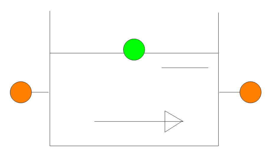
Fig. 6.11.1 Schematic of a heat tank (flow-trough).
Fall type
type label |
Description |
Active |
|---|---|---|
Heat tank |
Open flow-through tank |
No |
6.11.1. Mathematical model
This component represents a simple tank with an area \(A\) and an infinite height. The Heat Tank is an open flow-through tank with two inlets/outlets.
Furthermore, we assume:
The liquid in the tank has a uniform temperature over the whole volume. Thus, we assume perfect mixing.
The temperature of the outflowing liquid is equal to the temperature of the liquid in the tank (\(T_{out}\) = \(T\), with \(T\) the temperature of the liquid in the tank).
We apply the mixing rule to obtain the temperature change of the liquid in the tank if liquid is flowing into the tank.
We neglect the heat losses to the surrounding.
The liquid is flowing in the positive direction if enters the tank at inlet 1 and/or exits the tank at outlet 2 as indicated by the arrow.
The elevations of the centerline of the inlets/outlets of the tank equal the elevations of the connecting nodes.
The minimum fluid level is equal to the lowest inlet/outlet elevation. Fluid can only flow out of the tank on the side where the fluid level is above the elevation of a connecting node.
We consider two situations:
Both inlet/outlets are submerged, see Figure Fig. 6.11.2.
The fluid level is below one of the inlets/outlets, see Figure Fig. 6.11.3.
6.11.1.1. Submerged state
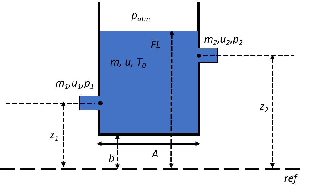
Fig. 6.11.2 Both inlet/outlet pipes are submerged.
Steady-state calculation
The following holds if both inlet/outlet pipes are submerged for the steady-state calculation.
Mass balance:
with \(\dot{m}\) the mass flow rate at a connection point.
Energy balance:
with \(u\) the specific internal energy.
Furthermore, the temperature of the outflowing liquid is equal to the temperature of the liquid in the tank \(T\) :
Finally, the following holds for the pressure difference between the two connection points in steady-state:
with \(A_1 = 0.25 \pi D_1^2\) and \(A_2=0.25 \pi D_2^2\) the area of the inlet and outlet pipe, respectively.
WANDA calculates the following quantities in a post-processing step at the end of the steady-state calculation:
Pressure in the tank:
\(p = p_2 + \rho(u) g (z_2-b) - \frac{\xi_2\dot{m}_2|\dot{m}_2| }{2 \rho A_2^2}\)
Fluid level in the tank:
\(FL =\frac{p}{g \rho(u)} + b\)
Temperature of the fluid in the tank:
\(T = T(u)\)
The mass of the fluid in the tank:
\(m = \frac{p A}{g}\)
Transient calculation
The pressure in the tank at the new time step is determined by:
where \(p_{old}\) is the pressure in the tank calculated at the end of the previous timestep.
The mass of the fluid in the tank at the new time step is determined by:
where \(m_{old}\) is the mass of the fluid in the tank calculated at the end of the previous timestep.
The temperature of the fluid in the tank at the new time step is determined by:
where \(T_{old}\) is the temperature of the fluid in the tank calculated at the end of the previous timestep.
The fluid level in the tank at the new time step is determined by:
6.11.1.2. Free inflow state
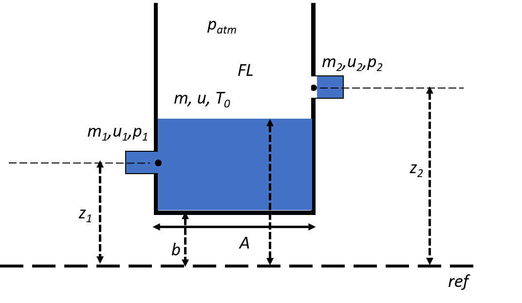
Fig. 6.11.3 Tank with free inflow.
It is not possible to drain the tank. Therefore, the minimum fluid level is equal to the the lowest elevation of the connecting nodes:
Remark:
It can occur that fluid entering the tank on one side immediately flow out on the other side of the tank if the fluid level is less or equal to elevation of the connecting nodes. Because WANDA determines the fluid level in a post-processing step, there could be a small discrepancy between the mass flow in/out of the tank and the change in fluid level.
6.11.2. Heat tank
6.11.2.1. Hydraulic specifications
Input properties
Description |
Input |
SI-units |
Remarks |
|---|---|---|---|
Bottom level |
real |
[m] |
|
Tank rea |
real |
[m2] |
|
Diameter of inlet 1 |
real |
[mm] |
|
Diameter of outlet 2 |
real |
[mm] |
|
Loss coefficient of inlet 1 |
real |
[-] |
|
Loss coefficient of outlet 2 |
real |
[-] |
6.11.2.2. Component messages
Message |
Type |
Explanation |
|---|---|---|
Fluid level is above the elevation of the inlet and outlet, and/or inflow from both sides |
Info |
Outflow is possible at both sides |
Fluid level is below the elevation of inlet 1 and no inflow from that side |
Info |
Not possible to have outflow if the fluid level is lower than the height of the inlet |
Fluid level is below the elevation of outlet 2 and no inflow from that side |
Info |
Not possible to have outflow if the fluid level is lower than the height of the outlet |
Fluid level is below the connecting node elevations and no inflow from both sides |
Info |
Not possible to have outflow if the fluid level is lower than the height of the inlet and outlet |