6.8. Heat buffer
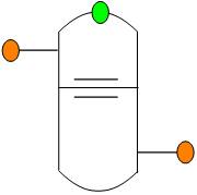
Fig. 6.8.1 Schematic overview of the heat buffer.
Fall type
Type label |
Description |
Active |
|---|---|---|
Heat pipe |
Buffer tank: Storage of thermal energy. |
No |
6.8.1. Mathematical models
The buffer tank is a model of a stratified buffer and can be used to store thermal energy. The stratified buffer is modelled with a hot and a cold zone, that are separated by an interface. In both zones the fluid is ideally mixed, but the zones never mix with each other. The interface between these two zones is tracked over time based on the in and outflow from the buffer tank. The fluid in the tank is assumed to be incompressible, therefore the volumetric inflow is equal to the volumetric outflow.

Fig. 6.8.2 Definition of the variables of the heat buffer.
The volume conservation is described by the following equation:
The volume conservation equation can be rewritten in core quantities as:
Volume will be conserved in both steady and transient simulations. The pressure difference between the two connection points is defined by:
in which:
variable |
Description |
Units |
|---|---|---|
\(P_1\) |
Pressure connection point 1 |
Pa |
\(P_2\) |
Pressure connection point 1 |
Pa |
\(\rho_h\) |
Density of the fluid on the hot side of the buffer |
kg/m3 |
\(\rho_c\) |
Density of the fluid on the cold side of the buffer |
kg/m3 |
\(z_1\) |
Height of connection point 1 |
m AD |
\(z_2\) |
Height of connection point 2 |
m AD |
\(I\) |
Level of the interface between the cold and hot water |
m AD |
The level of the interface needs to be known to solve equation (6.8.3). In steady state the interface level is given by the user. In transient calculations the change of the interface in time is calculated with:
in which:
variable |
Description |
Units |
|---|---|---|
\(I_{new}\) |
New level of the interface |
m AD |
\(I_{old}\) |
Level of the interface at the previous time step |
m AD |
\(A\) |
Area of the buffer |
m2 |
this can be rewritten in terms of a mass flow rate as:
Finally the equation for the heat stored in the buffer should be derived. The heat stored in the buffer can also be calculated with the assumption that the buffer is fully isolated, such that there is no heat loss to the surroundings. The energy stored on the hot side can be calculated from:
with \(u_1\) as the specific (\(J/kg\)) energy on the hot side. Equation (6.8.6) can also be derived for the cold side. The temperatur on both the hot and cold side can be calculated from the internal energy.
6.8.2. Heat buffer properties
6.8.2.1. Hydraulic specifications
Description |
Input |
SI-units |
Remarks |
|---|---|---|---|
Initial hot temperature |
real |
°C |
|
Initial cold temperature |
real |
°C |
|
Initial interface level |
real |
m AD |
This is the level of the interface between the hold and the cold water |
Inner diameter |
real |
m |
|
Top level |
real |
m AD |
|
Bottom level |
real |
m AD |
Remarks
The heat buffer will give an warning when it is fully charged or discharged. Whne it is fully charged or discharged you can continue to feed it but the outlfow temperature will change to either the hot temeprature or cold temperature depending if the buffer is fully charged or discharged.
6.8.2.2. Component specific output
Temperature hot side [°C]
Temperature cold side [°C]
Interface level [m AD]
6.8.2.3. Component messages
Message |
Type |
Explanation |
|---|---|---|
Hot temperature should be higher then or equal to the cold temperature |
error |
The user made an input error where the initial hot temperature is below the initial cold temperature |
The initial level of the interface should be higher than the bottom of the vessel |
error |
The user made an input error where the initial interface level is below the bottom of the vessel |
The initial level of the interface should be lower than the top of the vessel |
error |
The user made an input error where the initial interface level is above the top of the vessel |
The buffer is fully charged |
warning |
The interface level is at the bottom of the buffer and no additional heat can be stored in the tank |
The buffer is fully discharged |
warning |
The interface level is at the top of the buffer and no additional heat can be retrieved from the tank |
The buffer starts discharging |
info |
After the buffer is full, when the flow rate reverses the buffer will start discharging again |
The buffer starts charging |
info |
After the buffer has ben complety discharged, when the flow rate reverses the buffer starts charging again. |