6.1. HEAT domain
6.1.1. Core quantities
In the heat domain the following core quantities are used:
Total pressure \(p_t\) [N/m2]
mass flow rate \(\dot{m}\) [kg/s]
Specific internal energy \(u\) [J/kg]
The total pressure (\(p_t\)) is defined as:
and the mass flow rate (\(\dot{m}\)) is defined as:
The specific internal energy is a function of the temperature, \(T\):
It is used to calculate the amount of energy needed to raise the temperature of the fluid to another temperature. The amount of energy needed is the difference between the specific internal energy at the given temperatures:
The following symbols are used:
Variable |
Description |
Units |
|---|---|---|
p |
The manometric (or piezometric) pressure |
N/m2 |
\(\dot{m}\) |
mass flow |
kg/s |
\(\rho\) |
density |
kg/m3 |
g |
gravitational acceleration |
m/s2 |
h |
pressure head |
m |
v |
velocity |
m/s |
A |
cross sectional area |
m2 |
u |
specific internal energy |
J/kg |
\(T\) |
temperature |
K |
\(c_p\) |
specific heat at constant pressure |
J/kg K |
The pressure (p), discharge (Q), (energy) head (H) and temperature are derived from the above given core quantities. These core quantities are calculated as:
with:
Variable |
Description |
Units |
|---|---|---|
pt |
total pressure |
N/m2 |
Q |
discharge (volume flow) |
m3/s |
H |
energy head |
m |
z |
elevation |
m |
The temperature \(T\) in the user interface is displayed in degree Celsius. This is the only unit that can be chosen for temperature due to limitations in the unit system. Controls using temperature should also use degree Celsius.
6.1.2. Fluid properties
In Wanda Heat the properties of the fluid depend on the temperature. Therefore, a table with “Temperature dependent fluid properties” needs to be defined before starting any simulation (see Fig. 6.1.1). This table can be found in the “Fluid window” under the “Model” menu.
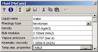
Fig. 6.1.1 Example of a fluid window.
Fluid window
The following properties depend on the actual temperature:
Density [kg/m3]
Kinematic viscosity [m2/s]
Vapour pressure [bar.a]
Specific heat [J/kg/K]
Thermal conductivity coefficient [W/mK]
The above properties of the fluid have to be specified within the computational range (the range of temperatures Wanda encounters during the computation). An error will be displayed if Wanda computes a temperature anywhere outside this range at any time (‘Temperature outside table range’).
It should be noted that Wanda linearly interpolates between the temperatures at which the values are specified in the table. An erroneous solution may result if the fluid properties do not vary linearly over the table rows (i.e., to few table rows are defined to capture the variation in fluid properties).
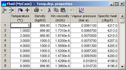
Fig. 6.1.2 Fluid table example
The fluid window contains also the property fields “Density”, “Vapour pressure” and “Kinematic viscosity”. These are ignored by WANDA Heat.
By default the fluid property table for water is loaded (stored in program directory Wanda4Property TemplatesExamplesFluids). The user might build a database of fluid properties to be loaded / saved in the fluid window. Fluid property template files can be loaded into the fluid properties window by clicking on the ‘open property template file’ button or pressing ‘Ctrl + o’ in the fluid window. In a similar way the user might save (key: ‘Ctrl + S’) fluid property templates.
6.1.3. Overview of Heat Components
The Heat components listed below are currently available in wanda. Your license specifies if you are authorised to use them.
Type |
Symbol |
Short description |
|---|---|---|
|
Vertically positioned, prismatic (constant area), nonvented air vessel |
|
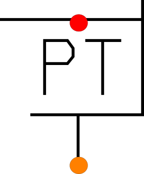
Heat boundary: Heat BoundPT |
|
Pressure temperature boundary condition |
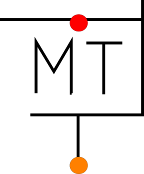
Heat boundary: Heat BoundMT |
|
Mass flow temperature boundary condition |
Heat boundary: Heat BoundT(PM) |
|
Temperature pressure or mass flow boundary condition |
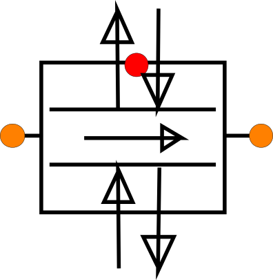
|
Ideal check valve; closes if \(Q < 0\), and opens if \(p_1 - p_2 > \Delta p_{reopen}\) |
|
Heat exchanger: Heat supply QHeat in |
|
Supply heat to or extract heat from the fluid by directly specifying a heat input. |
Heat exchanger: Heat supply Tdown |
|
Supply heat to or extract heat from the fluid by specifying a temperature at downstream Heat node. |
Heat exchanger: Heat supply QHeat with limits on T |
|
Supply heat to or extract heat from the fluid by directly specifying a heat input, with user specified limits for the minimum and maximum temperatures |
Heat exchanger: Heat exchanger |
|
Exchange heat with surroundings due to temperature difference between fluid and ambient temperature |
Heat exchanger: Heat demand |
|
Heat demand for district heating systems with different input parameters for heating and warmp (tap) water |
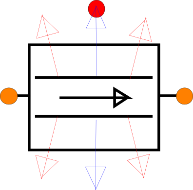
|
Heat pipe including friction model, friction generated heat and heat transfer to or from the surroundings. |
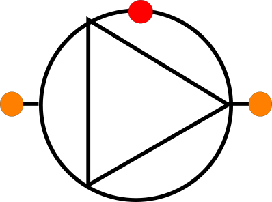
|
|
Complete pump model with various data and drives; positive and negative speed. |
|
|
Surge tower with storage area independent of liquid level. |
|
|
Surge tower with storage area independent of liquid level. |
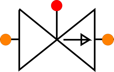
|
|
Control or block valve with choice out of four predefined Deltares standard head loss characteristics or user characteristics (Cv Kv, Xi). |
|
|
Converter to enable the connection of liquid component to heat components |
|
|
Exchange heat with surroundings due to temperature difference between fluid and ambient temperature. |
|
|
Exchange heat with surroundings due to temperature difference between fluid and ambient temperature. |
|
|
Supply heat to the fluid by gas combustion |
|
|
Heat supply via a solar collector |


6.1.4. Component properties
All input and output properties are displayed in the property window (selection property window: Shift-F11). The property window can be divided in 5 parts:
Part of property window |
Properties |
|---|---|
General input data |
Name, comment, keywords etc |
Component specific input data |
Type dependent |
Action table |
Type dependent for active types only (actions) |
General output data |
Messages, default HEAT output variables |
Component specific output data |
Type dependent (including pressure loss, temperature loss, mass) |
The default HEAT output variables (for each connect point) are: discharge, energy head, pressure, velocity, density, temperature and mass flow rate.
The visibility of some properties can be managed using the checkboxes in the upper part of the Mode & Options window in the “Model” menu.
The properties are type dependent. They are described for each component type separately. Some details about the action table are described below.
6.1.5. Hydraulic and thermal action tables
Hydraulic or thermal transients in a pipeline system are caused by changes in the flow conditions or thermal boundary conditions. These changes are initiated by manoeuvring Heat components in the system, called actions. Not all components in a pipeline system can be activated. A component is categorised as either an active or a passive component, depending on its manoeuvrability.
An action is described using a control parameter specified as a function of time. The control parameter depends on the component type. In WANDA, a control parameter function is specified through an action table in the properties of the component or by connecting a control system, see WANDA Control. The control system overrules the component specific action table.