4.4. Air Vessel
4.4.1. AIRVha (class)

Fig. 4.4.1 Horizontal vented air vessel
Supplier type
Type label |
Description |
active |
|---|---|---|
Airvessel horizontal vented |
Horizontally positioned, cylindrical, vented air vessel |
No |
4.4.1.1. Mathematical model
A horizontal air vessel or air chamber with air inlet (vented air chamber) can be modelled by the same equations as the air vessel without air inlet (see “AIRVhn (class)” on page 203) as long as the fluid level is higher than the air inlet level. When the fluid level is below the air inlet level the air vessel behaves like the ‘surge tower’ and the air pressure remains atmospheric.
As long as the fluid level is above the air inlet level the governing equations are:
and:
with:
variable |
Description |
Units |
|---|---|---|
P |
absolute air pressure |
N/m2 |
V |
air volume |
m3 |
k |
Laplace coefficient |
‑ |
C |
constant |
Nm if k = 1 |
The Laplace coefficient depends on the thermodynamic behaviour of the air. Isothermal expansion is described by k = 1. Adiabatic expansion is described by k = 1.4.
If the fluid level is below the air inlet level the behaviour is governed by (4.4.2) solely. In steady state the air vessel does not supply fluid. The governing equation then is:
4.4.2. Airvessel horizontal vented
4.4.2.1. Hydraulic specifications
description |
input |
unit |
range |
default |
remarks |
|---|---|---|---|---|---|
top level |
real |
[m] |
|||
diameter |
real |
[-] |
(0-100] |
||
length |
real |
[m] |
(0-100] |
See remarks |
|
air inlet level |
real |
[m] |
See remarks |
||
Laplace coefficient |
Real |
[-] |
[1-1.4] |
See also: “Mathematical model” Section 4.4.1.1.
Remarks
”Top level” and “air inlet level” are related to the horizontal reference plane.
The air inlet level depicts the level where the air inlet enters the airvessel.
An airvessel in WANDA is modelled with a straight instead of rounded sides. The volume of the real airvessel and the WANDA airvessel should be the same. The length used for input should therefore be smaller than the length of the real airvessel, depending on its shape.
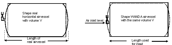
Fig. 4.4.2 Assumption in the length of an airvessel.
4.4.2.2. Component specific output
Fluid level [m]
Air pressure (absolute) [N/m2.abs]
4.4.2.3. H-actions
None
4.4.2.4. Component messages
Message |
Type |
Explanation |
|---|---|---|
Air inlet level not in between top and bottom level of air chamber |
Error |
The air inlet level must be in between the top and bottom level, in order to have a defined amount of air in the vessel. |
Empty air chamber |
Error |
The fluid level has dropped below the bottom. The storage area becomes zero and further calculations can not be carried out. |
Air inlet closes |
Info |
The fluid level has risen above the air inlet level. Air compression starts to be taken into account. |
Air inlet opens |
Info |
The fluid level has dropped below the air inlet level. Air decompression is no longer taken into account. |
Air inlet is closed |
Steady state |
The initial fluid level is above the air inlet level. |
Air inlet is open |
Steady state |
The initial fluid level is below the air inlet level. |
4.4.3. AIRVhn (class)

Fig. 4.4.3 Horizontal non-vented air vessel
Supplier type
type label |
description |
active |
|---|---|---|
Airvessel horizontal non-vented |
Horizontally positioned, cylindrical, non-vented air vessel |
No |
4.4.3.1. Mathematical model
A horizontal air vessel or air chamber without air inlet can be modelled by two equations just as the vertical chamber.
The first equation describes the behaviour of the enclosed air:
with:
variable |
Description |
Units |
|---|---|---|
P |
absolute air pressure |
N/m2 |
V |
air volume |
m3 |
k |
Laplace coefficient |
‑ |
C |
constant |
Nm if k = 1 |
The Laplace coefficient depends on the thermodynamic behaviour of the air. Isothermal expansion is described by k = 1. Adiabatic expansion is described by k = 1.4.
The second equation governs the amount of supplying discharge Q:
in which Vf denotes the fluid volume. Note that this equation is different from the (4.4.2) for vertical chambers. This is due to the fact the storage surface of a horizontal chamber is not constant.
The minus sign indicates that the chamber supplies fluid to the system when the fluid level is decreasing in time.
(4.4.5) can also be formulated as:
where variable V refers to the air volume. In steady state the air vessel does not supply fluid. Hence in steady state the governing equation is:
4.4.4. Airvessel horizontal non-vented
4.4.4.1. Hydraulic specifications
description |
Input |
unit |
range |
default |
remarks |
|---|---|---|---|---|---|
top level |
real |
[m] |
|||
diameter |
real |
[m] |
(0 100] |
||
length |
real |
[m] |
(0-100] |
See remarks |
|
air quantity by |
Fluid Level/ Air volume/ Constant C |
See remarks |
|||
initial fluid level |
real |
[m] |
If “air quantity by” = Fluid Level |
||
initial air volume |
real |
[m3] |
If “air quantity by” = Air volume |
||
initial C in P*V = C |
real |
[J] |
If “air quantity by” = Constant C |
||
Laplace coefficient |
real |
[-] |
[1-1.4] |
See also: “Mathematical model” Section 4.4.3.1.
Remarks
”Top level” and “air inlet level” are related to the horizontal reference plane.
The air volume and the fluid level in the airvessel are determined by either the initial fluid level, the initial air volume or the initial constant C. One quantity has to be given by the user, the other two quantities are calculated by Wanda. Isothermal behaviour is assumed during the steady state computation.
An airvessel in WANDA is modelled with a straight instead of rounded sides. The volume of the real airvessel and the WANDA airvessel should be the same. The length used for input should therefore be smaller than the length of the real airvessel, depending on its shape.
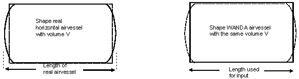
Fig. 4.4.4 Real airvessel shape versus modelled airvessel shape.
4.4.4.2. Component specific output
Fluid level [m]
Air pressure (absolute) [N/m2.abs]
Air volume [m3]
4.4.4.3. H-actions
None
4.4.4.4. Component messages
Message |
Type |
Explanation |
|---|---|---|
Initial fluid level not in between top and bottom level of air chamber |
Error |
This is an input error. |
Empty air chamber |
Error |
The fluid level has dropped below the bottom. The storage area becomes zero and further calculations can not be carried out. |
Accuracy not obtained in computing fluid level as function of volume with bisection method |
Warning |
4.4.5. AIRVva (class)

Fig. 4.4.5 Vertical vented air vessel
Supplier type
type label |
description |
active |
|---|---|---|
Airvessel vertical vented |
Vertically positioned, prismatic (constant area), vented air vessel |
No |
4.4.5.1. Mathematical model
A vertical air vessel or air chamber with air inlet (vented air chamber) can be modelled by the same equations as the air vessel without air inlet (see “AIRVhn (class)” on page 203) as long as the fluid level is higher than the air inlet level. However when the fluid level is below the air inlet level the air vessel behaves like the ‘surge tower’ and the air pressure remains atmospheric.
As long as the fluid is above the air inlet level the governing equations are:
with:
variable |
Description |
Units |
|---|---|---|
P |
absolute air pressure |
N/m2 |
V |
air volume |
m3 |
k |
Laplace coefficient |
‑ |
C |
constant |
Nm if k = 1 |
and:
in which Aav denotes the storage surface and xf the fluid level in the air chamber with respect to the global co-ordinate system. The minus sign indicates that the chamber supplies fluid to the system when the fluid level is decreasing in time.
When the fluid level is below the air inlet level the governing equation is simply:
For steady state calculations the air vessel does not supply fluid and hence the equation for steady state is simply:
4.4.6. Airvessel vertical vented
4.4.6.1. Hydraulic specifications
description |
Input |
unit |
range |
default |
remarks |
|---|---|---|---|---|---|
top level |
real |
[m] |
See remarks |
||
bottom level |
real |
[m] |
See remarks |
||
air inlet level |
real |
[m] |
See remarks |
||
chamber area |
real |
[m2] |
(0.001-100] |
||
Laplace coefficient |
real |
[-] |
[1-1.4] |
See also “Mathematical model” Section 4.4.5.1.
Remarks
The “Bottom level” is used to check if the vessel becomes empty during the simulation; that means that “Bottom level” is the allowed minimum fluid level.
The meaning depends on the constructive design of the vessel; see pictures below
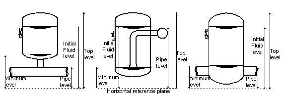
Fig. 4.4.6 The air inlet level depicts the level where the air inlet enters the airvessel.
An airvessel in WANDA is modelled with a straight instead of a rounded top and bottom. The volume of the real airvessel and the WANDA airvessel should be the same. The top and bottom level should therefore be taken respectively lower and higher than the level of the real airvessel. How much lower and higher depends on the shape of the real airvessel.
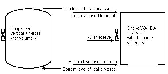
Fig. 4.4.7 Real airvessel shape versus modelled airvessel shape.
Meaning of Pressure in property window Airvessel defined in Fig. 4.4.8 and
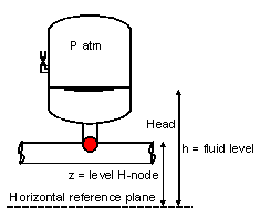
Fig. 4.4.8 Definition of pressure in an airvessel.
Variable |
Description |
|---|---|
Head |
Head in H-node of airvessel |
Pressure P |
Pressure in H-node relative to atmosphere \(\rho g (H-z)\) |
z |
Height of the H-node |
H |
Fluid level |
Air pressure |
Absolute air pressure \(\rho g (H-h) + P_{\text{atm}}\) |
Component specific output
Fluid level [m]
Air pressure (absolute) [N/m2.abs]
H-actions
None
4.4.6.2. Component messages
Message |
Type |
Explanation |
|---|---|---|
Air inlet level not in between top and bottom level of air chamber |
Error |
The air inlet level must be in between the top and bottom level, in order to have a defined amount of air in the vessel. |
In computation of initial fluid level. Check input data |
Error |
has been violated somehow. |
Empty airchamber |
Warning |
Computation can continue, since storage area is constant independent of the height. The results will not be physically correct, but may assist in the further design of the air vessel. |
Air inlet closes |
Info |
The fluid level has risen above the air inlet level. Air compression starts to be taken into account. |
Air inlet opens |
Info |
The fluid level has dropped below the air inlet level. Air decompression is no longer taken into account. |
4.4.7. AIRVvn (class)

Fig. 4.4.9 Vertical non-vented air vessel
Supplier type
Type label |
description |
active |
|---|---|---|
Airvessel vertical non-vented |
Vertically positioned, prismatic (constant area), non-vented air vessel |
No |
4.4.7.1. Mathematical model
A vertical air vessel or air chamber without air inlet can be modelled by two equations. The first equation describes the behaviour of the enclosed air:
with:
variable |
Description |
Units |
|---|---|---|
P |
absolute air pressure |
N/m2 |
V |
air volume |
m3 |
k |
Laplace coefficient |
‑ |
C |
constant |
Nm if k = 1 |
The Laplace coefficient depends on the thermodynamic behaviour of the air. Isothermal expansion is described by k = 1. Adiabatic expansion is described by k = 1.4.
The second equation governs the amount of supplying discharge Q:
in which Aav denotes the storage surface and xf the fluid level in the air chamber with respect to the global co-ordinate system. The minus sign indicates that the chamber supplies fluid to the system when the fluid level is decreasing in time.
In steady state the air vessel does not supply fluid. Hence in steady state the governing equation is:
4.4.8. Airvessel vertical non-vented
4.4.8.1. Hydraulic specifications
description |
Input |
unit |
range |
default |
remarks |
|---|---|---|---|---|---|
top level |
real |
[m] |
See remarks |
||
bottom level |
real |
[m] |
See remarks |
||
chamber area |
real |
[m2] |
(0.0001-100] |
||
air quantity by |
Fluid Level/ Air volume/ Constant C |
See remarks |
|||
initial fluid level |
real |
[m] |
If ”air quantity by” = Fluid Level |
||
initial air volume |
real |
[m3] |
If “air quantity by” = Air volume |
||
initial C in P*V = C |
real |
[J] |
If “air quantity by” = Constant C |
||
Laplace coefficient |
real |
[-] |
[1-1.4] |
See also “Mathematical model” Section 4.4.7.1.
Remarks
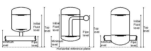
Fig. 4.4.10 The air inlet level depicts the level where the air inlet enters the airvessel.
The air volume and the fluid level in the airvessel are determined by either the initial fluid level, the initial air volume or the initial constant C. One quantity has to be given by the user, the other two quantities are calculated by Wanda. Isothermal behaviour is assumed during the steady state computation.
An airvessel in WANDA is modelled with a straight instead of a rounded top and bottom. The volume of the real airvessel and the WANDA airvessel should be the same. The top and bottom level should therefore be taken respectively lower and higher than the level of the real airvessel. How much lower and higher depends on the shape of the real airvessel.
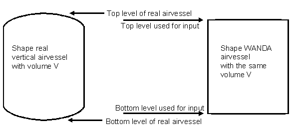
Fig. 4.4.11 Real airvessel shape versus modelled airvessel shape.
Meaning of Pressure in property window Airvessel defined in Fig. 4.4.12 and
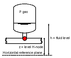
Fig. 4.4.12 Definition of pressure in an airvessel.
Variable |
Description |
|---|---|
Head |
Head in H-node of airvessel |
Pressure P |
Pressure in H-node relative to atmosphere \(\rho g (H-z)\) |
z |
Height of the H-node |
H |
Fluid level |
Air pressure |
Absolute air pressure \(\rho g (H-h) + P_{\text{atm}}\) |
4.4.8.2. Component specific output
Fluid level [m]
Air pressure (absolute) [N/m2.abs]
Air volume [m3]
4.4.8.3. H-actions
None
4.4.8.4. Component messages
Message |
Type |
Explanation |
|---|---|---|
Top level below bottom level |
Error |
This is obviously an input error. |
Initial fluid level not in between top and bottom level of air chamber |
Error |
This is an input error. |
Empty airchamber |
Warning |
Computation can continue, since storage area is constant independent of the height. The results will not be physically correct, but may assist in the further design of the air vessel. |
4.4.9. Airvessel Vertical Hybrid (class)
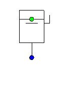
Fig. 4.4.13 Airvessel vertical hybrid
Fall type
type label |
description |
active |
|---|---|---|
Airvessel vertical hybrid |
Vertically oriented air vessel with an air valve |
No |
4.4.9.1. Mathematical model
The hybrid air vessel is a combination of a non-vented air vessel and an air valve at a strategic elevation. When the fluid level is above the air valve level, the component is governed by the same equations as the non-vented air vessel (see “AIRVvn (class)” on page 209). However, when the fluid reaches the air valve level, the air is expelled via the air valve. The user specifies the initial fluid level/air volume/constant C in steady state, which means that the air valve level can be reached when the air pressure is still greater than the atmospheric pressure. The capacity of the air valve is modelled by the discharge coefficient and in/outflow area. The hybrid air vessel is especially useful in long distance pipelines, in which the initial stage of the transient is the most critical stage. The initial wave front is much flatter, because of the large air volume. The air valve prevents the air expanding into system in the later stages of the transient scenario.
As long as the fluid is above the air valve level, the governing equations are:
with:
variable |
Description |
Units |
|---|---|---|
P |
absolute air pressure |
N/m2 |
V |
air volume |
m3 |
k |
Laplace coefficient |
‑ |
C |
constant |
Nm if k = 1 |
The Laplace coefficient depends on the thermodynamic behaviour of the air. Isothermal expansion is described by k = 1. Adiabatic expansion is described by k = 1.4.
The second equation governs the amount of supplying discharge Q:
in which Aav denotes the storage surface and xf the fluid level in the air chamber with respect to the global coordinate system. The minus sign indicates that the chamber supplies fluid to the system when the fluid level is decreasing in time.
When the fluid level is below the air valve level the change of air volume in time is dependent of two phenomena. First, the compression/expansion of the air, secondly the amount of air leaving/entering the system. This state is modelled as the air valve with a certain residual volume (see “VENT (class)” on page 435). The residual volume equals the volume between the air valve elevation and the top of the air vessel. The air leaving/entering the system is determined by equations (4.4.17) to (4.4.20).
1. Subsonic air flow in: \(0,53 < \frac{P}{P_{0}} < 1,0\)
with:
variable |
Description |
Units |
|---|---|---|
\(A\) |
Discharge area (air) |
m2 |
\(C\) |
Discharge coefficient (air) |
|
\(P\) |
Absolute internal pressure on fluid level |
Pa |
\(P_0\) |
Atmospheric pressure |
Pa |
\(R\) |
Gas constant |
J kg-1 K-1 |
\(T_0\) |
Ambient air temperature |
K |
\(Q_{air}\) |
Air flow (positive if into system: supplier!) |
m3/s |
2. Critical flow in: \(\frac{P}{P_{0}} < 0,53\)
3. Subsonic air flow out: \(1,0 < \frac{P}{P_{0}} < \frac{1}{0,53}\)
with:
Variable |
Description |
Units |
|---|---|---|
k |
Laplace coefficient (ratio of specific heats) |
4. Critical flow out: \(\frac{P}{P_{0}} > \frac{1}{0,53}\)
For steady state calculations the air vessel does not supply fluid and hence the equation for steady state is simply:
4.4.10. Airvessel vertical hybrid properties
4.4.10.1. Hydraulic specifications
description |
Input |
unit |
range |
default |
remarks |
|---|---|---|---|---|---|
Top level |
real |
[m] |
|||
Bottom level |
real |
[m] |
(0 100) |
||
Air inlet level |
real |
[m] |
(0-100) |
||
Chamber area |
real |
[-] |
(0.0001-100) |
||
Air quantity by |
Fluid Level/ Air volume/ Constant C |
See remarks |
|||
Initial fluid level |
real |
[m] |
If “air quantity by” = Fluid Level |
||
Initial air volume |
real |
[m3] |
If “air quantity by” = Air volume |
||
Initial C in P*V = C |
real |
[J] |
If “air quantity by” = Constant C |
||
Laplace coefficient |
real |
[-] |
[1-1.4] |
||
Ambient air temperature |
real |
[°C] |
|||
Air discharge coeff. |
real |
[-] |
|||
Air discharge area |
real |
[m2] |
See also help on using the Property Window.
Remarks
“Top level”, “Bottom level”, “Air inlet level” and “initial fluid level” are related to the horizontal reference plane.
The air volume and the fluid level in the air vessel are determined by the initial fluid level, the initial air volume or the initial constant C. The user specifies either one of these properties. The other two quantities are calculated by WANDA.
If the user specifies the initial fluid level/air volume/constant C such that the air inlet level is reached when the pressure inside the air chamber is higher than the atmospheric pressure, the air will be expelled via the air inlet. This results in a decreasing C (see equation 1).
4.4.10.2. Component specific output
Fluid level [m] (relative to datum)
Air volume [m3] -
Air temperature [°C] -
Air pressure [Pa] -
4.4.10.3. H-actions
None
4.4.10.4. Example
The hybrid air vessel in the example below has the following specifications:
Propperty |
Value |
|---|---|
Top level |
20 m |
Bottom level |
6 m |
Air inlet level |
9 m |
Chamber area |
8 m2 |
Air quantity by: |
Constant C. C = 21600 kJ |
Laplace coefficient |
1.20 |
Ambient temperature |
15 °C |
Air discharge coeff. |
0.9 |
Air discharge area |
0.01770 m2 |
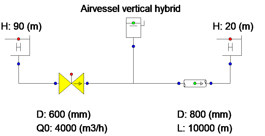
Fig. 4.4.14 Schematic overview of the modeled system.
The valve closes in 3 seconds.
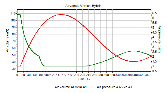
Fig. 4.4.15 Result of valve closure on the air volume and air pressure in the hybrid airvessel.
The air vessel dampens the initial pressure wave, such that the air pressure drops from 6.4 bara to 2.0 bara in 65 s. After 75 s of simulation the air valve level is reached and air is being expelled from the vessel to prevent draining of the air vessel. The graph shows that the air pressure reaches atmospheric pressure at t = 95 s. The downstream boundary condition is large enough to smoothly shut the air valve after 340 s.
4.4.10.5. Component messages
message |
explanation |
|---|---|
ERROR: Initial fluid level not in between top and bottom level of air chamber |
Input error. Keep in mind that the air vessel is inclined and that the fluid level is still relative to the horizontal reference plane. |
ERROR: Initial fluid level inconsistent with steady head |
The initial fluid level is below the air inlet level and inconsistent with the pressure head. |
WARNING: empty air chamber |
The fluid level has dropped below the bottom. The storage area becomes zero and further calculations cannot be carried out. |
WARNING: Accuracy not obtained in computing fluid level as function of volume with bisection method |
This warning should not normally occur and is intended to warn the programmer. |
WARNING: Initial fluid level below air valve level. Air pressure is atmospheric. |
|
INFO: Air inlet is closed |
|
INFO: Air inlet is open |
|
INFO: Air inlet opens |
|
INFO: Air inlet closes |