4.3. Hydraulic nodes
4.3.1. General
An H-node connects two or more H-components which each other. In the diagram this H-node is represented by a connection line, connected to the hydraulic connect point of a H-component (blue dot). In case more than two connect points have to be connected the H-node is compounded of a master and one or more slave connection lines, thus forming a tree. For more information about the connection line, see “Connecting components” on page 34.
4.3.2. Pressure definition for H-node
In the H-node the main variable H (Head) is calculated from a set of equations as explained in “Implementation” on page 157. The pressure P is derived from this head according Bernouilli (see “Bernoulli’s theorem” on page 148).
The total pressure is derived from this total head, according to:
with
Variable |
Description |
Units |
|---|---|---|
\(P_{\text{total}}\) |
Total pressure |
N/m2 |
\(\rho_g\) |
Fluid density |
kg/m3 |
\(H\) |
Total head |
m |
\(z\) |
Elevation of H-node |
m |
The pressure in the connect points of the adjacent H-components are derived from the pressure of the H-node. If the adjacent H-component has a diameter property (e.g: VALVE, PIPE), the velocity v can be determined and thus, the velocity head can be taken into account. Please note that only the velocity head of pipes which are flowing into the node is taken into account, according:
Because the diameters of the adjacent H-components may differ or the elevation of the centreline (in case of PIPE) may differ, the local pressure in the individual connect points may differ. From a mathematical view the connect points and the H-node is the same location.
The H-node model knows the elevation and diameters of the adjacent H-components. For all adjacent components the lowest pressure is computed at the soffit.
The pressure shown for the H-node is the lowest connect point pressure.
Example:
In the system below the discharge (Q) is 884 m3/h. In the Mode & Options menu the pressure output reference (only used for PIPE output) is set to “centreline”.
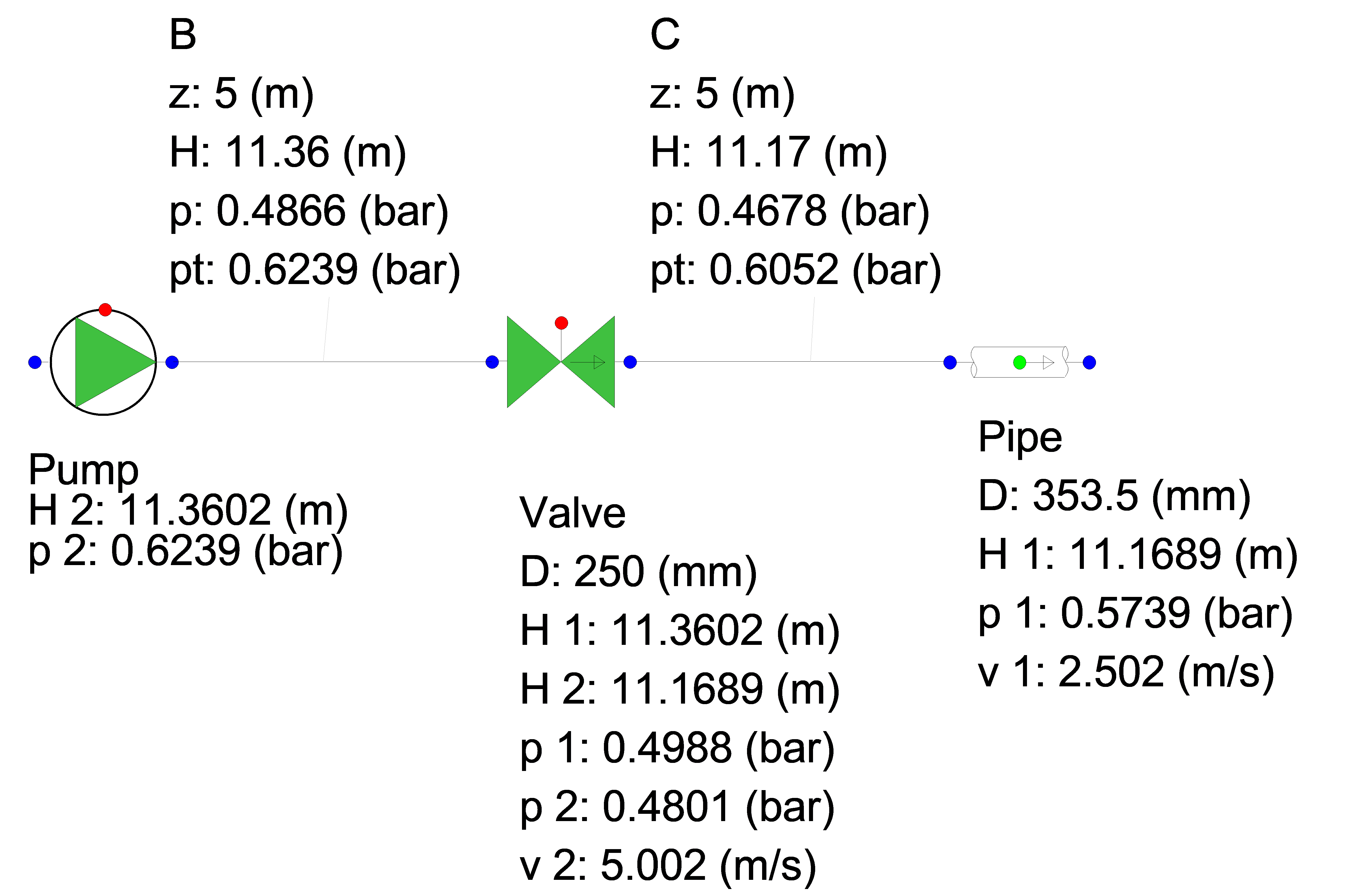
Consider H-node C and adjacent H-components:
Property |
Value |
|---|---|
The energy head (or total head) |
11.17 m |
Elevation of H-node and elevation begin of pipe |
5 m |
Velocity head of Valve |
\(\frac{v^{2}}{2 g}=\frac{5 \times 5}{2 \times 9.81}=1.27 m\) |
Velocity head in Pipe |
\(\frac{v^{2}}{2 g}=\frac{2.5 \times 2.5}{2 \times 9.81}=0.32 \mathrm{~m}\) |
Pressure downstream side Valve |
\(P=1000 \times 9.81 \times(11.17-5.00-1.27)=0.480\) barg |
Pressure upstream side Pipe at CL |
\(P=1000 \times 9.81 \times(11.17-5.00-0.32)=0.574\) barg |
Total Pressure in H-node C |
\(P=1000 \times 9.81 \times(11.17-5.00)=0.605\) |
Lowest pressure in H-node C based on soffit location: Valve |
\(P=1000 \times 9.81 \times(11.17-5.00-1.27-0.125)=0.468\) barg |
Pipe |
\(P=1000 \times 9.81 \times(11.17-5.00-0.32-0.177)=0.556\) barg |
Lowest pressure at Valve is shown in the property window
4.3.3. Cavitation in H-node
If the pressure drops below the vapour pressure, cavitation occurs(see “Cavitation” on page 176). Cavitation in an H-node is only taken into account if the H-node is connected to a PIPE.
The H-node model knows the elevation and diameters of the adjacent H-components. For all adjacent components the lowest pressure is computed at the soffit. If this lowest pressure drops below the vapour pressure, cavitation occurs.
The lowest pressure in an H-node is computed according:
with:
Variable |
Description |
Units |
|---|---|---|
\(P_{\text{lowest}}\) |
Total pressure |
N/m2 |
\(\rho\) |
Fluid density |
kg/m3 |
\(g\) |
Gravitational acceleration |
m/s2 |
\(H\) |
Total head |
m |
\(Z_{\text{soffit}, i}\) |
Soffit of “diameter-defined” H-component i |
m |
\(v_{i}\) |
Velocity at begion or end of H-component i |
m/s |
The void fraction is expressed as the cavitation vapour volume divided by the sum of the half-element volumes of the adjacent pipes.
4.3.4. Standard output of H-node types
Standard output for each type of H-node is:
Head [m]
Pressure [N/m2] (the lowest pressure of the connected H-components)
Node specific output for the H-node is:
Total Pressure [N/m2]
Void fraction [-]
4.3.5. Available H-node types
The following types of H-nodes are available and are described in next sections:
H-node
H-node with initial head
H-node with conditional initial head
H-node with demand
4.3.6. H-node
This H-node is the standard hydraulic node, by default generated after connecting of two H-components.
The output (H and P) can be calculated if the H-node is part of a fully connected (“open”) hydraulic network with one or more a boundary conditions for the Head (e.g. BOUNDH, TANK). “Open” means that each H-component has a certain relation between head and discharge and that there is at least one component prescribing the head or pressure.
Input properties
Description |
Input |
unit |
remarks |
|---|---|---|---|
Elevation |
Real |
[m] |
Messages
Message |
Message |
Explanation |
|---|---|---|
Cavitation in steady state not allowed |
error |
The lowest pressure in the H-node is less than the vapour pressure |
Pressure < Pvapour; Cavitation not supported for H-node without PIPE connections |
warning |
In this H-node there is no PIPE component connected. The cavitation model needs at least 1 PIPE to compute the vapour volume. This warning is only given the first time the pressure condition is true; the rest of the simulation is physically invalid. |
Cavitates |
informative |
H-node starts cavitating; that means that the lowest pressure becomes less than the vapour pressure |
Cavitation collapses |
informative |
Void fraction becomes 0 |
Change Type to Hydraulic node with initial head |
error |
H-node is part of an isolated part of the network in which no information is available for the head; the user must define the head in this part of the model. See “H-node with initial head” on page 198. |
4.3.7. H-node with initial head
If the H-node is part of a “closed” or “”isolated” hydraulic network, there is no connection with a boundary condition like a BOUNDH and the actual head in the steady state computation can not be determined.
This is explained in the figure below: the head in the H-nodes U1, U2 and U3 can not be calculated.
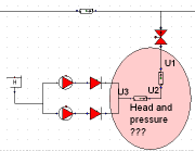
Fig. 4.3.2 Schematic overview of a Wanda model with a closed section.
It is therefore necessary to define the head for this area in one of the H-nodes. It is up to the user which H-node head will be prescribed (changed into the type: H-node with initial head).
Note: if this “isolated network” occurs during the transient computation, the head of the previous time step will be used.
The type of the H-node can be changed via the property window (drop down list in “Type” field)
Input properties
Description |
Input |
unit |
remarks |
|---|---|---|---|
Elevation |
Real |
[m] |
|
Initial head |
Real |
[m] |
Messages
Message |
Message |
Explanation |
|---|---|---|
Cavitation in steady state not allowed |
error |
The lowest pressure in the H-node is less than the vapour pressure |
Pressure < Pvapour; Cavitation not supported for H-node without PIPE connections |
warning |
In this H-node there is no PIPE component connected. The cavitation model needs at least 1 PIPE to compute the vapour volume. This warning is only given the first time the pressure condition is true; the rest of the simulation is physically invalid. |
Cavitates |
informative |
H-node starts cavitating; that means that the lowest pressure becomes less than the vapour pressure |
Cavitation collapses |
informative |
Void fraction becomes 0 |
4.3.8. H-node with conditional initial head
If the H-node is part of a “closed” or “”isolated” hydraulic network, there is no connection with a boundary condition like a BOUNDH and the actual head in the steady state computation cannot be determined.
Fig. 4.3.3 shows that the head in the H-nodes U1, U2 and U3 cannot be calculated.
Fig. 4.3.3 Boundary condition error in a closed network.
It is therefore necessary to define the head for this area in one of the H-nodes. It is up to the user which H-node head will be prescribed (changed into the type: H-node with initial head). However when using for example the parameter script is can be useful that the node only describes the pressure and temperature when they are part of an isolated system. For this purpose the conditional init H node can be used. This node only pre describes its head when it is part of an isolated system. Note: if this “isolated network” occurs during the transient computation, the head of the previous time step will be used. The type of the H-node can be changed via the property window (drop down list in “Type” field)
Input properties
Description |
Input |
unit |
remarks |
|---|---|---|---|
Elevation |
Real |
[m] |
|
Initial head |
Real |
[m] |
Messages
Message |
Message |
Explanation |
|---|---|---|
Cavitation in steady state not allowed |
error |
The lowest pressure in the H-node is less than the vapour pressure |
Pressure < Pvapour; Cavitation not supported for H-node without PIPE connections |
warning |
In this H-node there is no PIPE component connected. The cavitation model needs at least 1 PIPE to compute the vapour volume. This warning is only given the first time the pressure condition is true; the rest of the simulation is physically invalid. |
Cavitates |
informative |
H-node starts cavitating; that means that the lowest pressure becomes less than the vapour pressure |
Cavitation collapses |
informative |
Void fraction becomes 0 |
4.3.9. H-node with demand
The H-node will subtract a demand volume flow from the network. This node is very useful for modelling drinking water distribution networks over a longer period of time and the application is comparable to the EPANET approach.
With this node the volumetric base demand can be specified as the discharge to end-users connected to this node. The pattern can be used to vary the actual (instantaneous) discharge over time (e.g. high peaks during morning and evening but low at night). The pattern will be repeated if the simulation time is larger than the table period.
Input properties
Description |
Input |
unit |
remarks |
|---|---|---|---|
Base demand |
Real |
[m3/s] |
|
Pattern |
Choice |
[-] |
See remarks |
Table |
Table |
[-] |
See remarks |
For Pattern the user can select either a constant value or time-value pattern specified via the table.
Messages
Message |
Message |
Explanation |
|---|---|---|
Cavitation in steady state not allowed |
error |
The lowest pressure in the H-node is less than the vapour pressure |
Pressure < Pvapour; Cavitation not supported for H-node without PIPE connections |
warning |
In this H-node there is no PIPE component connected. The cavitation model needs at least 1 PIPE to compute the vapour volume. This warning is only given the first time the pressure condition is true; the rest of the simulation is physically invalid. |
Cavitates |
informative |
H-node starts cavitating; that means that the lowest pressure becomes less than the vapour pressure |
Cavitation collapses |
informative |
Void fraction becomes 0 |