4.16. Merger
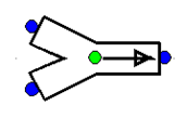
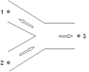
Fig. 4.16.1 Schematic wanda component merger
type label |
description |
active |
|---|---|---|
2-merger |
Three-node junction which merges 2 separate branch flows into a combined flow. Cross section can be circular or rectangular. |
no |
The merger differs from the Y-junctions (Section 4.40) because there is no straight main flow. The area of the three legs may be different.
Instead of negative flow the Merger component acts as a Splitter component (Section 4.27).
4.16.1. Mathematical model
4.16.1.1. Positive flow definition
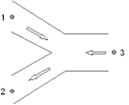
The positive flow definition and the numbers of the connect points is important to understand the results in the property window. Notice that the connect point numbering of the Merger differs from that of the Splitter (Section 4.27).
For the Merger-junction the positive flow definition and connect point numbers are defined in the figure below.
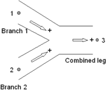
Fig. 4.16.2 Merger-junction positive flow direction and connection points.
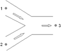
4.16.1.2. Flow regimes
The Merger supports only the positive merging flow and for negative flow the splitting variant. The other flow regimes are not supported and for these circumstances the local losses are ignored, that means the Merger becomes frictionless.
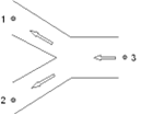
In the table below the different flow regimes are explained with a scheme with corresponding actual flow arrows.
Table 1: definition of different flow regimes
Merging flow (Positive flow) |
|
Splitting flow (Negative flow) |
|
Not supported flow regimes |
|
Not supported flow regimes |
|
4.16.1.3. Equations
The head loss over a 3-node component depends on the distribution of the discharges and the area of the connected legs. The Merger supports only the user specified resistance coefficient Xi (ξ) depending on discharge ratio’s for a fixed area ratio.
The head loss in 3-node components is a function of the combined flow in the combined leg. Including the continuity equation (no production or loss of mass in the component) the general set of the three equations of the Y-junction is:
Where:
Q i = total discharge in leg i |
[m3/s] |
|---|---|
Hi = energy head in connect point i |
[m] |
Ai = pipe area leg i (leg with total flow) |
[m2] |
ξij = loss coefficient between point i and j |
[-] |
The subscripts (1), (2) and (3) correspond to the different legs.
For negative splitting flow the formulas of the Splitter component (Section 4.27) will be used with Q1 taken into account instead of Q3.
For the not supported flow regimes the head loss equation becomes H1-H3 = 0 and H2-H3 = 0
4.16.2. Merger properties
The input and output properties for both types are specified below.
Input properties
Description |
input |
unit |
range |
default |
Remarks |
|---|---|---|---|---|---|
Cross section |
Circular Rectangular |
Circular |
|||
Diameter combined leg |
Real |
[mm] |
If Cross section = Circular |
||
Diameter merge branch 1 |
Real |
[mm] |
If Cross section = Circular |
||
Diameter merge branch 2 |
Real |
[mm] |
If Cross section = Circular |
||
Width combined leg |
Real |
[mm] |
If Cross section = Rectangular |
||
Height combined leg |
Real |
[mm] |
If Cross section = Rectangular |
||
Width merge branch 1 |
Real |
[mm] |
If Cross section = Rectangular |
||
Height merge branch 1 |
Real |
[mm] |
If Cross section = Rectangular |
||
Width merge branch 2 |
Real |
[mm] |
If Cross section = Rectangular |
||
Height merge branch 2 |
Real |
[mm] |
If Cross section = Rectangular |
||
Xi method |
Formula Table |
If Xi method = Formula, the following input should be defined:
Description |
input |
unit |
range |
default |
Remarks |
|---|---|---|---|---|---|
Angle |
15 30 45 |
De definition of the angle is shown in Fig. 4.16.3.
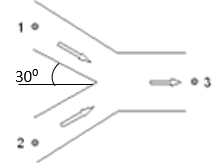
Fig. 4.16.3 Definition of the angle
If Xi method = Table, the following input should be defined:
Description |
input |
unit |
range |
default |
Remarks |
|---|---|---|---|---|---|
Xi tables valid for |
Splitting Merging Both |
||||
Xi splitting branch 1 |
Table (ξ12) |
if Xi tables = Splitting or Both |
|||
Xi splitting branch 2 |
Table (ξ13) |
if Xi tables = Splitting or Both |
|||
Xi merging branch 1 |
Table (ξ21) |
if Xi tables = Merging or Both |
|||
Xi merging branch 2 |
Table (ξ31) |
if Xi tables = Merging or Both |
Example of Xi table (valid for Area ratio = 0.5); Merging branch 1 (ξ13)
Discharge ratio |
Xi |
|---|---|
[-] |
[-] |
0.0 |
0.90 |
0.2 |
0.12 |
0.4 |
0.39 |
0.6 |
0.92 |
0.8 |
1.48 |
1.0 |
2.08 |
Component specific output properties
Loss coefficient branch 1 [-] |
The ξ13 for positive flow and ξ31 for negative flow |
|---|---|
Loss coefficient branch 2 [-] |
The ξ23 for positive flow and ξ32 for negative flow |
Head loss branch 1 [m] |
The ΔH13 for positive flow and ΔH31 for negative flow |
Head loss branch 2 [m] |
The ΔH23 for positive flow and ΔH32 for negative flow |
Component messages
Message |
Type |
Explanation |
|---|---|---|
Merging flow |
Info |
|
Splitting flow |
Info |
|
Not supported flow regime |
Info |
|