4.14. Inclined Air Vessel
4.14.1. Inclined air vessel (class)
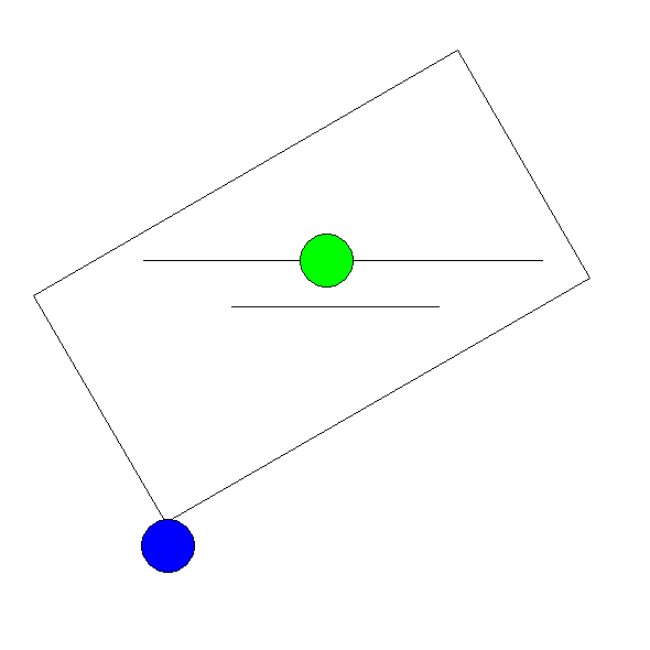
Fig. 4.14.1 Inclined air vessel
Supplier type
type label |
description |
active |
|---|---|---|
Inclined air vessel |
Air vessel with a cylindrical volume oriented at an angle with the horizontal plane |
No |
4.14.1.1. Mathematical model
An inclined air vessel or air chamber without air inlet can be modelled by two equations.
The first equation describes the behaviour of the enclosed air:
with:
variable |
Description |
Units |
|---|---|---|
P |
absolute air pressure |
N/m2 |
V |
air volume |
m3 |
k |
Laplace coefficient |
‑ |
C |
constant |
Nm if k = 1 |
The Laplace coefficient depends on the thermodynamic behaviour of the air. Isothermal expansion is described by k = 1. Adiabatic expansion is described by k = 1.4.
The second equation governs the amount of supplying discharge Q:
in which Vf denotes the fluid volume. Note that this equation is different from the equation for vertical chambers. This is due to the fact the storage surface of an inclined chamber is not constant (it’s a function of the fluid level).
The minus sign indicates that the chamber supplies fluid to the system when the fluid level is decreasing in time.
(4.14.2) can also be formulated as:
where variable V refers to the air volume. In steady state the air vessel does not supply fluid. Hence in steady state the governing equation is:
Note: for an inclination angle of 0 degr, the model coincides with the horizontal non-vented airvessel; for an inclination angle of 90 degr, the model coincides with the vertical non-vented airvessel.
4.14.2. Airvessel inclined non-vented
4.14.2.1. Hydraulic specifications
description |
Input |
unit |
range |
default |
remarks |
|---|---|---|---|---|---|
Bottom level |
real |
[m] |
|||
Inner diameter |
real |
[m] |
(0 100) |
||
Inner length |
real |
[m] |
(0-100) |
See remarks |
|
Relative head depth |
real |
[-] |
(0-1) |
See remarks |
|
Inclination |
real |
[º] |
(0-90) |
||
Number of vessels |
integer |
[-] |
(1-10) |
See remarks |
|
Air quantity by |
Fluid Level/ Air volume/ Constant C |
See remarks |
|||
Initial fluid level |
real |
[m] |
If “air quantity by” = Fluid Level |
||
Initial air volume* |
real |
[m3] |
If “air quantity by” = Air volume |
||
Initial C in P*V = C |
real |
[J] |
If “air quantity by” = Constant C |
||
Laplace coefficient |
real |
[-] |
[1-1.4] |
See also help on using the Property Window.
* All inclined air vessel input is specified per vessel. Some output is specified for all vessels combined.
Remarks
”Bottom level” and “initial fluid level” are related to the horizontal reference plane.
The air volume and the fluid level in the air vessel are determined by the initial fluid level, the initial air volume or the initial constant C. The user specifies either one of these properties. The other two quantities are calculated by WANDA. Isothermal behaviour is assumed during the steady state computation.
The inclined air vessel is modelled in WANDA as a cylindrical element. The length is specified by the length of the cylindrical part of the vessel combined with two offsets to account for the volume in the spherical ends of the vessel (See figure below). The offsets are calculated using the ratio between the inner radius (R) and the depth of the ellipsoidal vessel head (Fd). The relative head depth is specified by (Fd/R). The effective length of the vessel is L + 2 x 0.666 x Fd. The equivalent length (offset) of a cylinder with the same volume as the vessel head is 0.666 x Fd.
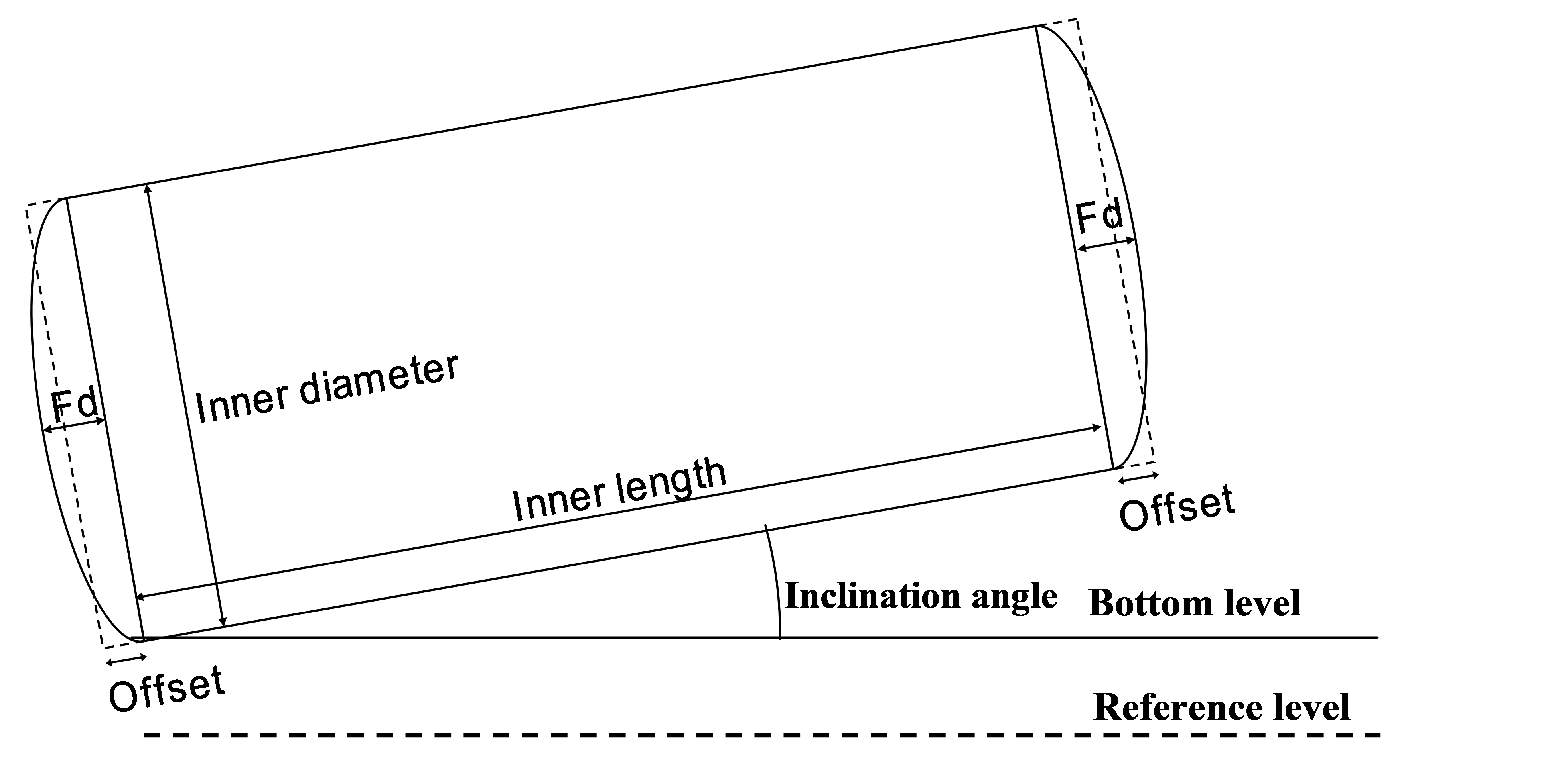
Fig. 4.14.2 Definition of variables for an inclined airvessel
It is possible to specify the number of air vessels at this location. The air vessels are treated as one large vessel in WANDA. It may however facilitate the user input. For horizontal vessels this could also be achieved by multiplying the length with the number of vessels and for vertical vessels by multiplying the storage area with the number of vessels. Please note that the initial condition settings should be specified for a single vessel.
The inclination determines the storage area as a function of the fluid level in the vessel. Several different curves may exist depending on the dimensions of the vessel. Some examples are shown in the graph below (L = 20 m, D = 5 m) . The different curves may result in bends in the air vessel dynamic behaviour.
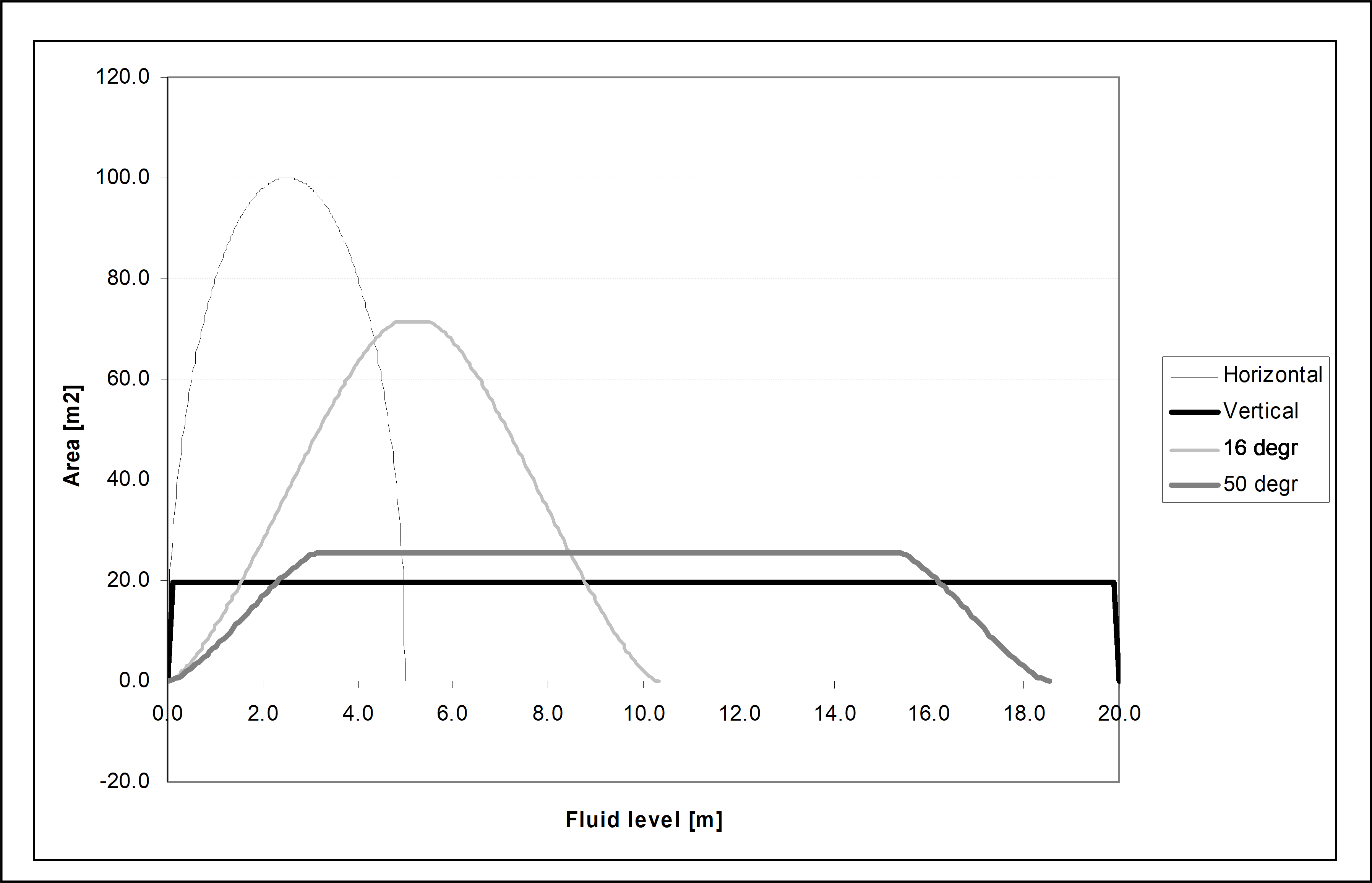
Fig. 4.14.3 Effect of inclinination on the area as function of the fluid level.
4.14.2.2. Component specific output
Liquid level [m] (relative to datum!)
Air volume [m3] All vessels combined
Storage area [m2] All vessels combined
Air pressure [Pa] -
Note: The air volume and storage area output are shown for all vessels together. The air pressure differs from the H-node pressure because of the difference in elevation between the H-node and the liquid level.
4.14.2.3. H-actions
None
4.14.2.4. Example
For the surge protection of a 100 km pipeline 3 inclined air vessels are simulated using the following model. The air vessels are represented in the model by one component. The vessel properties are shown in the figure below. The inclination of the vessel relative to the horizontal plane is 20 degrees. The front to depth ratio is 0.2.
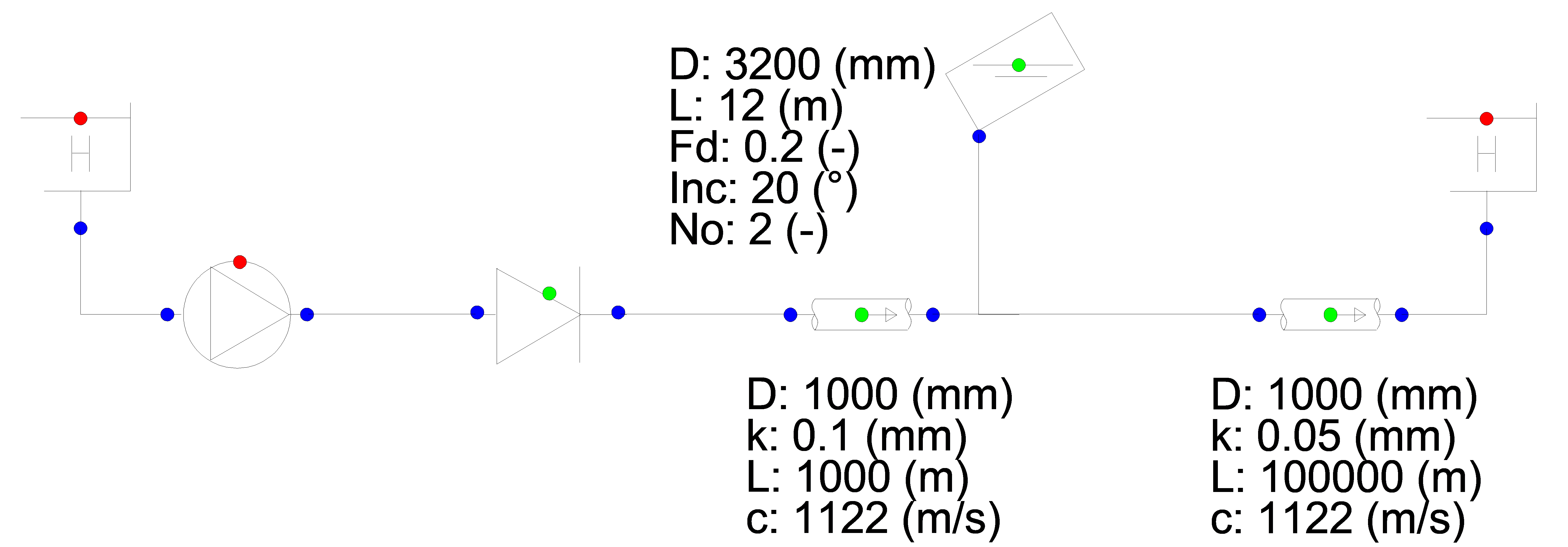
Fig. 4.14.4 Schematic overview of the example system.
The figure below shows the fluid level and the storage area in the inclined air vessel. The storage initially increases with decreasing fluid level, remains constant for a short period and ultimately decreases at the lowest fluid levels.
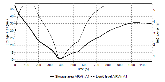
Fig. 4.14.5 Storage area and water level over time for the example system.
4.14.2.5. Component messages
message |
explanation |
|---|---|
ERROR: Initial fluid level not in between top and bottom level of air chamber |
Input error. Keep in mind that the air vessel is inclined and that the fluid level is still relative to the horizontal reference plane. |
ERROR: empty air chamber |
The fluid level has dropped below the bottom. The storage area becomes zero and further calculations can not be carried out. |
WARNING: Accuracy not obtained in computing fluid level as function of volume with bisection method |
This warning should not normally occur and is intended to warn the programmer. |