4.35. Vent, Air valve
4.35.1. VENT (class)

Fig. 4.35.1 Vent (air inlet and/or outlet)
Supplier type
type label |
description |
active |
|---|---|---|
VENT (discharge coeff.) |
Vent with the possibility of air in/outlet, air inlet only or air outlet only Capacity specified with discharge coefficients |
No |
VENT (inflow/outflow char.) |
Vent with the possibility of air in/outlet, air inlet only or air outlet only Capacity specified by inflow/outflow characteristics |
No |
4.35.1.1. Mathematical model
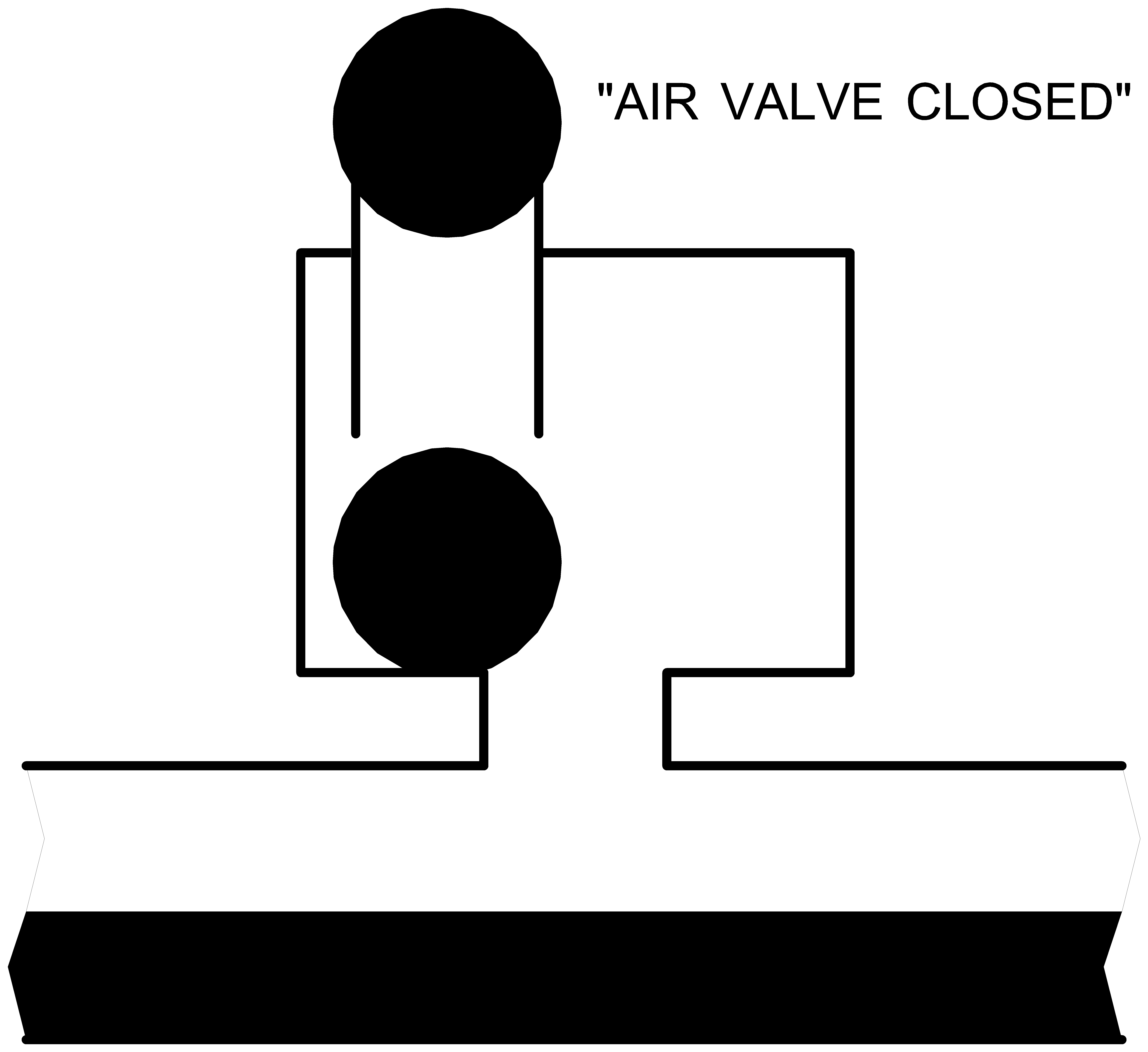
The vent or air valve is a component through which air can enter into or be expelled from the hydraulic system. This is usually achieved by a floating-ball valve mechanism (figures 1, 2 and 3). The purpose of the vent is to prevent cavitation or intolerable under pressures.
|
|
Figure 1: In/outlet vent in air inlet status |
Figure 2: In/outlet vent in air outlet status |
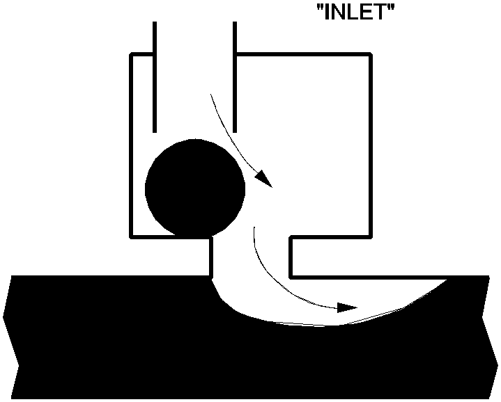
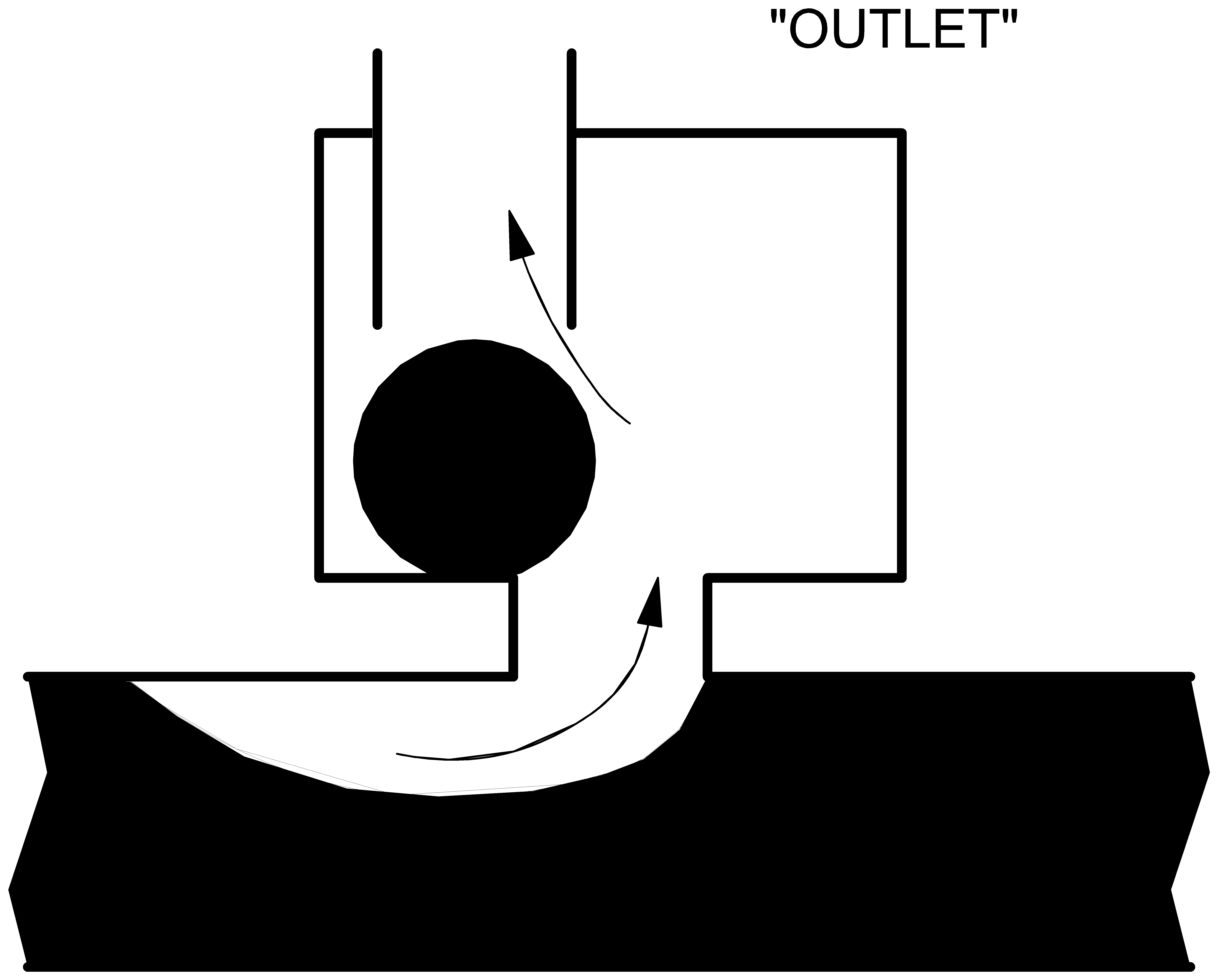
If the internal pressure in the system drops below the elevation of the vent, the floating-ball valve opens and air can enter the system (figure 1). The air entering the system will expand due to the internal pressure being lower than atmospheric pressure. If the air remains in the vicinity of the vent (e.g. in case the vent is located at a “high” point in the system) it will be expelled through the same vent if the internal pressure rises again above the elevation of the vent (figure 2). In this case all entered air will be expelled through the same vent. Meanwhile the air will also be compressed due to the internal pressure being higher than atmospheric. The vent closes at the instant the amount of expelled air is equal to the amount of entered air (figure 3). This type of vent is denoted by “in/outlet”.
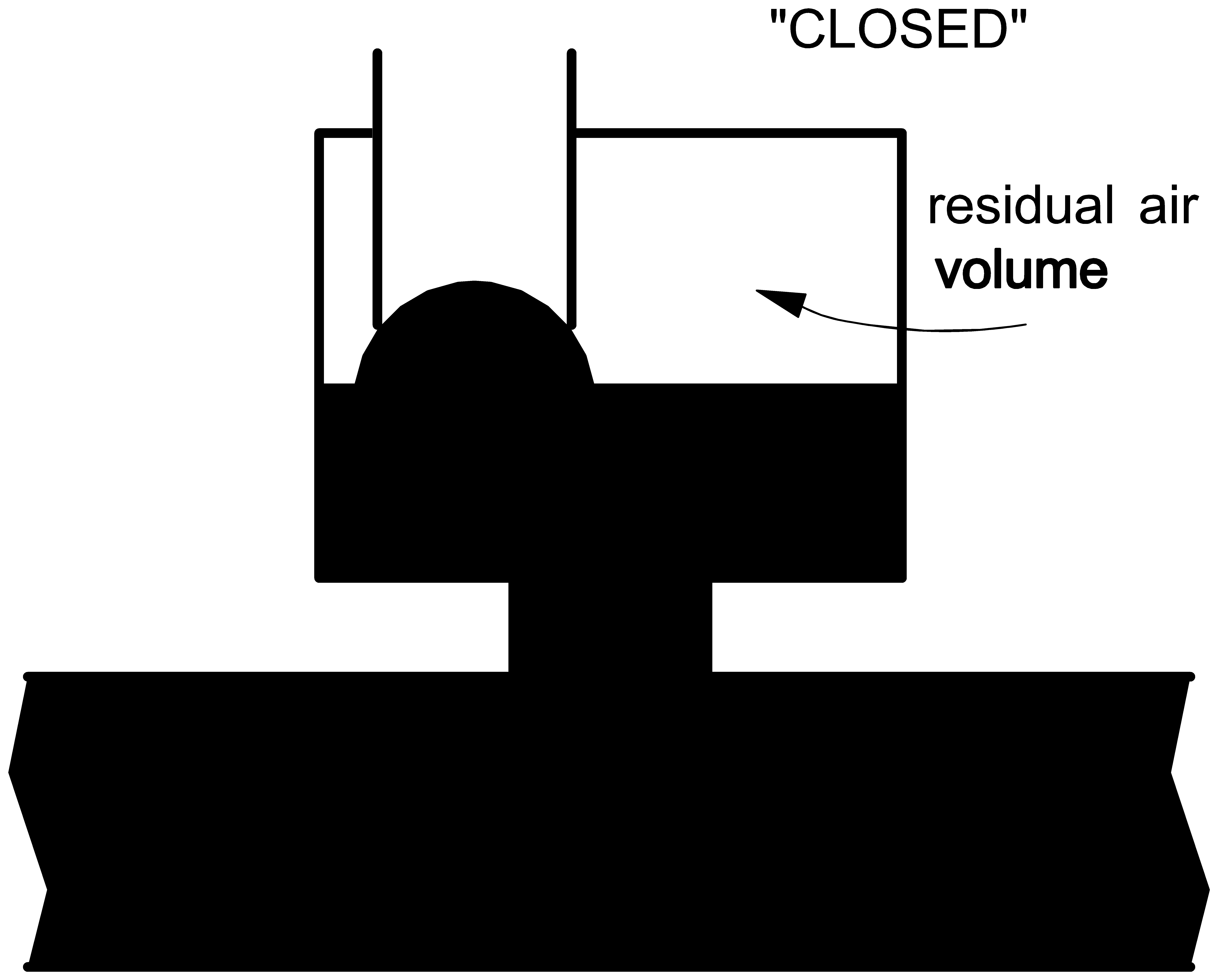
Fig. 4.35.2 In/outlet vent in closed status
If, however, the fluid flow causes the air to be moved away from the vent, the air will not be expelled through the vent. As soon as the system pressure rises again above the vent elevation the vent closes. This type of vent is denoted by “inlet”. The vent types “in/outlet” and “inlet” are in fact not different physically, but only circumstantially.
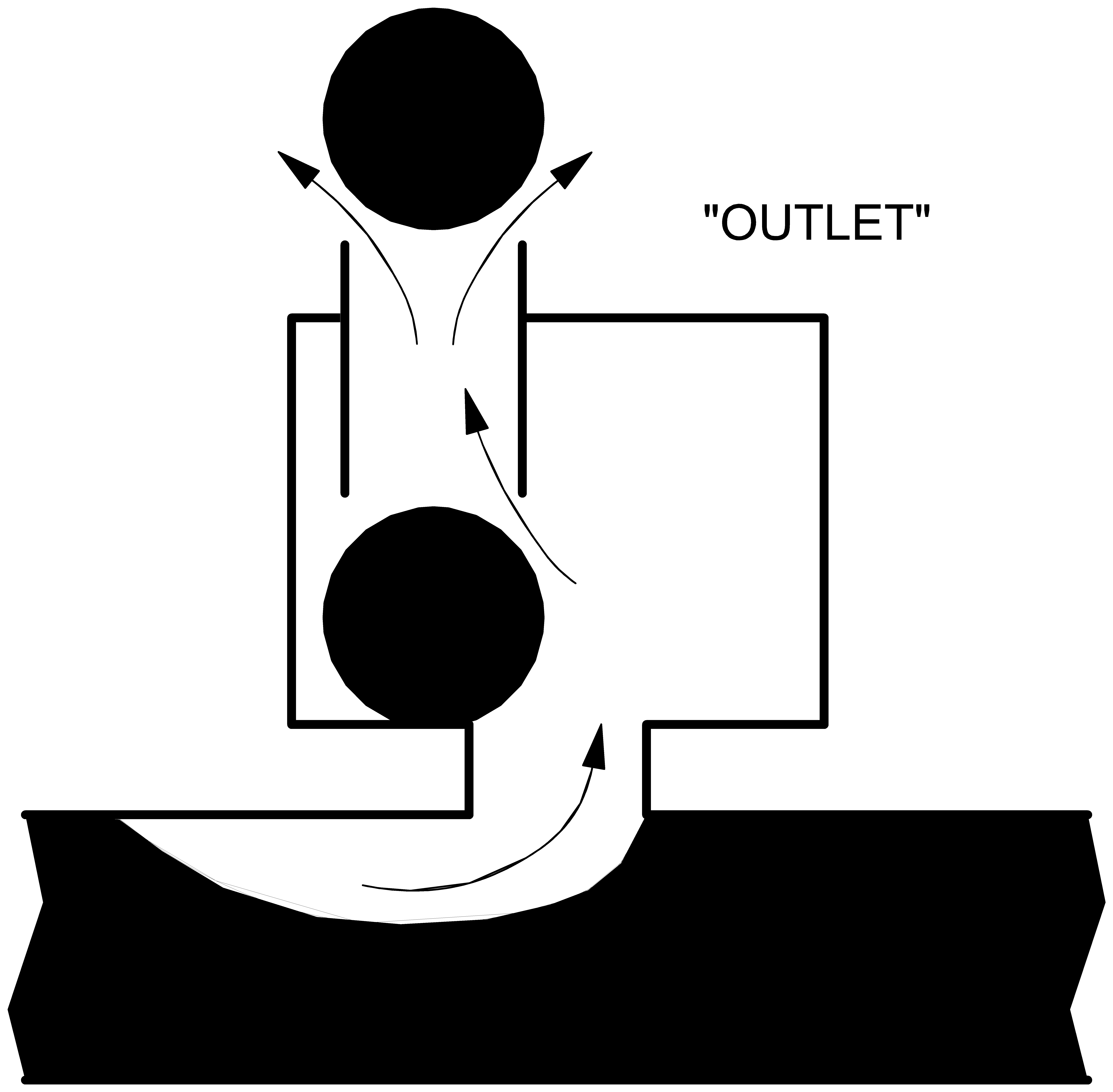
A third option is the vent that only allows air to be expelled from the system (figure 4). This is achieved by adding an “air check valve” to the vent. This valve is closed if the internal system pressure is below vent elevation (figure 5). A “sane” computation has to start with a positive initial air volume. This type of vent is denoted by “outlet”.
|
|
Figure 4: Outlet vent in air outlet status |
Figure 5:Outlet vent in closed air outlet status |
The air flow is compressible, with the consequence that due to local occurrence of supersonic velocities and shock waves, choking flow may arise. The air inlet capacity is therefore truncated to a certain level after which further reducing the internal pressure does not increase the air flow anymore. The expansion and compression of the air may be isothermal, adiabatic or polytropic. Since wanda is not a two-phase flow computer code it is not capable of describing the entrance and transportation of air in the pipeline as such. This means that the vent model is merely a boundary condition describing a pressure-discharge relation. In reality the amount of liquid within the system decreases when air enters the system. In the discharge supplied by the vent to the system the compressibility of the air is taken into account. The vent component supplies liquid to the system and therefore an error in the momentum balance (inertia forces) will be introduced. This error is small however if the amount of air is small compared to the pipeline volume. The continuity balance is not violated.
Changing water levels due to air entrance or expansion/compression can be taken into account by specifying a level-area table. This table represents the storage area in the components in the neighbourhood of the VENT against the fluid level drop. As the entered volume of air increases, the fluid level drops according to this level-area table. If the fluid-level is taken into account (user-specified), then air enters the system more difficult and is expelled more easily, compared to the situation without fluid-level effect.
For the description of the mathematical model four states are defined:
closed floating ball valve,
air inlet,
air outlet,
manual outlet.
In case of “closed-in” air (states 1 and 4) the component behaves like an air vessel with adiabatic expansion and compression:
in which:
P |
= |
absolute air pressure on fluid level |
[N/m2] |
V |
= |
air volume |
[m3] |
k |
= |
Laplace coefficient (ratio of specific heats) |
[-] |
C |
= |
Constant |
[Nm] |
The second equation governs the amount of supplying discharge Q:
In the “open” states 2 and 3 the change of air volume in time is dependent of two phenomena. Firstly the compression/expansion of the air, secondly the amount of air leaving/entering the system. The former is handled in the same way as with states 1 and 4. The latter is determined by either formula (3) to (6) or by the air valve characteristic, depending on which vent component has been selected. Both options are described here.
Vent (capacity defined by coefficients)
Subsonic air flow in
in which:
Ain |
= |
inlet area |
[m2] |
Cin |
= |
inlet discharge coefficient |
[-] |
P |
= |
abs. internal pressure on fluid level |
[Pa] |
P0 |
= |
atmospheric pressure |
[Pa] |
R |
= |
gas constant |
[J/kg⋅K] |
T0 |
= |
ambient air temperature |
[K] |
Qair |
= |
air flow (positive if into system: supplier!) |
[m3/s] |
Critical flow in
Subsonic air flow out
in which:
Aout |
= |
outlet area |
[m2] |
Cout |
= |
outlet discharge coefficient |
[-] |
k |
= |
Laplace coefficient (ratio of specific heats) |
[-] |
Critical flow out
Vent (capacity defined by characteristic)
The capacity of the vent can also be defined by the air valve characteristic (see example characteristic). In this case, you can define both the characteristic for inflow and outflow, which ever is applicable. The characteristic should be supplied as pressure against discharge.
Note: Often the characteristic supplied by the manufacturer will have the axes reversed from this definition. See also the example characteristic in this manual.
[CHART]
For both types of vents, the air volume is initialised by:
in which:
Vinit |
= |
Initial air volume to be expelled |
[atmospheric m3] |
Vres |
= |
Residual air volume |
[m3] |
If, according to equation (2), the air volume V becomes ≤ Vres the vent closes. If the system pressure head H drops below the vent elevation h the vent enters the inlet state. If the system pressure rises again above the vent elevation the vent enters the outlet state.
Following table may be helpful to decide which combination of VENT type and initial state must be chosen.
Scenario |
VENT type |
Initial state |
upstream pump trip or valve closure with automatic inlet/outlet VENTs without initial air volumes. |
In/outlet |
closed |
final stage of a slow filling procedure with inlet/outlet VENTs. ‘Slow’ means ‘slowly relative to the system’s characteristic time’. See remarks below. |
In/outlet |
outlet |
upstream pump trip or valve closure with automatic inlet VENTs without initial air volumes. |
Inlet |
closed |
final stage of a slow filling procedure with outlet VENTs. ‘Slow’ means ‘slowly relative to the system’s characteristic time’. See remarks below. |
Outlet |
outlet |
start-up scenario’s or downstream valve closure with automatic outlet VENTs and initial air volumes; steady state pressure must be sub-atmospheric. |
Outlet |
manual |
fast filling procedures or venting procedure with manually operated outlet VENTs. If the steady state pressure is super-atmospheric, then the VENTs open the first transient timestep. See remarks below. |
Outlet |
manual |
Remarks
The initial state ‘Inlet’ should only be used if no other combination seems appropriate.
The difference between the initial states outlet and manual is the steady state computation. The manual initial state of vent type outlet computes a steady state flow of 0 m3/s through the VENT. During the transient calculation the VENT starts to expel air from the system (if steady pressure is super-atmospheric) causing pressure waves in the system.
This manual initial state can be used to simulate a manual vent, which is closed in steady state and starts with air outlet at t = 0 s. The difference with the closed initial state, is the presence of an initial air volume in the system, which cannot be specified in the closed initial state. The outlet initial state is used to simulate the outlet of an air volume in the system. It computes a hydrodynamic balance between the VENT outflow and the pipe flows in steady state.
This balance is a realistic simulation, only if the air volume in the real system is large enough, i.e. if the outflow of this air volume requires a period, which is greater than 5 times the characteristic time of the system. The characteristic time of the system is 2 times the characteristic length divided by the average wave propagation speed. By taking a small residual air volume the simulation starts at the moment the large air volume has almost entirely left the system through the vent.
If you want to investigate the difference between both initial states, it is recommended to build a simple model and compare the transient results of both initial states (the initial air volume should be set sufficiently high and the level effect should be set to NO).
4.35.2. VENT (discharge coeff.)
4.35.2.1. Hydraulic specifications
description |
Input |
unit |
range |
default |
remarks |
elevation offset |
Real |
[m] |
See remark |
||
Laplace coefficient |
Real |
[-] |
[1-1.4] |
||
ambient air temperature |
Real |
[°C] |
|||
inlet discharge coefficient |
Real |
[-] |
(0-1] |
See remark |
|
outlet discharge coefficient |
Real |
[-] |
(0-1] |
See remark |
|
inlet discharge area |
Real |
[m2] |
≥0 |
||
outlet discharge area |
Real |
[m2] |
≥0 |
||
initial air volume |
Real |
[m3] |
[0-10] |
atmospheric m3 |
|
residual air volume |
Real |
[m3] |
[0-1] |
||
type |
In/outlet Inlet Outlet |
In/outlet |
See remark |
||
initial state |
Closed Inlet Outlet Manual |
Closed |
|||
level effect |
YES NO |
YES |
|||
level-area table |
table |
See remark |
See also “Mathematical model” on page 435.
Remark
The point of reference for the elevation offset of the vent is the geometric height of the H-node connecting the vent to the rest of the system.
Please be aware that for deriving the discharge coefficients Cin and Cout from a Kv-value (m3/h if = 1 bar) the manufacturer most probably specifies the capacity in atmospheric cubic metres per second. In general, the discharge coefficients describe the amount of contraction of the air flow through the orifices and will probably be in the range of 0.5 to 1.0.
The in/out type should be chosen, if the air enters and leaves the system at the same location. The inlet type should be chosen, if the air enters the system at the VENT location and is transported with the flow. The outlet type should be chosen, if the air leaves the system at the VENT location (high point) and can not enter the system. The outlet can be used in particular for the simulation of de-aeration procedures with manually operated VENT type, in combination with the manual initial state.
This data input template is based on a “sharing” concept. That is, the type can be changed without the need to re-enter the other data items. The consequence of this is that not all data are required for each type. For instance the outlet loss coefficient is not required in case the type is “inlet”. However, for the program to be able to determine that the input data are complete, all fields must be filled by the user.
The level-area table has the elevation offset of the vent as point of reference. At positive distances below this point of reference the area of (part of) the horizontal cross-section of the pipeline is given. This area determines where in the pipelines the air volume will form if air enters the system through the vent. It does not necessarily have to be equal to the cross-section of the pipe. For example, if the flow pushes the air volume to a corner of the pipeline the area at some levels will be smaller then the cross-section of the pipeline. The user must make an educated guess on where the air volume will form in the system. An estimation of the cross-section of an oblique pipeline is made by the volume of the pipeline times the height of the pipeline. The area at the lowest level-drop that is given will be used for the rest of the pipeline. If an abrupt change in area occurs, the two different areas should be ascribed to two levels with only a small distance between them.
The level-area table models the storage area of the pipes and components in the neighbourhood of the VENT with level effect. The storage area of all components should be modelled in which air may collect during air inlet. The following examples may be helpful on specifying the level-area table.

Fig. 4.35.3 Schematised pipe bridge.
The figure above shows a schematised pipe bridge with a length of 5 m. All pipe diameters are 1.5 m. The elevation offset is 0 in this example. The first column of the level-area table is the level drop relative to the offset elevation and must start with level drop 0 (area may be greater than 0). The second column represents the storage area at a fluid level, which is “level drop” m below the vent elevation. The storage area of the horizontal circular pipe is discretised at 3 intermediate levels with an average length of 6.5 m. The storage area of the two vertical pipes increases as the level drops from 0 to 1.5 m. Consequently following table is entered for the situation above.
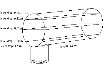
Fig. 4.35.4 Example sketch of the level drop table
Example of level drop table:
Level drop [m] |
area [m2] |
|---|---|
0.0 |
0.0 |
0.22 |
7.31 |
0.75 |
9.75 |
1.28 |
7.31 |
1.5 |
1.76 |
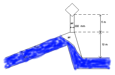
Fig. 4.35.5 Schematization of a sawtooth pipeline
The figure above shows a schematised sawtooth pipeline with a height of 10 m. The offset of the vent is 5 m. The diameter of the connecting pipeline is 0.2 m, all other pipelines have a diameters 5.4 m. At a level drop of 5 m, the area changes gradually from 0.03 m2 to 1.76 m2. Because of the flow, the air volume will be pushed in the corner and downwards in the short pipeline. All this information is used in the level-area table. Below the level drop of 0.4 m the area remains 0.355 m2 for 10 m, until the direction of the main pipeline changes to horizontal. This provides with a large enough volume for the air that enters the system.
Example of level drop table
Level drop [m] |
area [m2] |
|---|---|
0.0 |
0.03 |
5.0 |
0.03 |
5.1 |
1.76 |
5.3 |
0.4 |
5.4 |
0.355 |
Important Notice: In case of vents with large capacity it is well possible to have a very sensitive computation in which small pressure differences cause large air flows and volumetric effects. Although the program is optimised to find the most accurate solution, numerical oscillations may still occur (inertia is not taken into account). In that case it is up to the user, to adjust (reduce) the time step and the convergence criteria to reduce the oscillations.
See also “Mathematical model” on page 435.
4.35.2.2. Component specific output
Air volume [m3]
Air flow [m3/s]
Air pressure (absolute) [N/m2.abs]
Air temperature [°C]
4.35.2.3. H-actions
None
4.35.2.4. Component messages
Message |
Type |
Explanation |
Positive initial air volume not allowed in combination with “initial state = closed” |
Error |
|
Contradiction between type and initial state |
Error |
|
“Initial state = outlet” not possible with zero initial air volume |
Error |
|
Starts in closed phase |
Info |
|
Absolute pressure below vapour pressure |
Error |
This would lead to an infinite air volume. This error can only occur if the vent is connected to a boundh or other H prescribing component. |
Closes |
Info |
The floating ball valve closes. |
Starts in air inlet phase |
Info |
|
Air inlet |
Info |
System pressure has dropped below the vent elevation. |
Starts in air outlet phase |
Info |
|
Air outlet |
Info |
System pressure has risen above the vent elevation and not all air has yet been expelled. |
Starts with closed air valve |
Info |
|
Air valve closes |
Info |
There may still be air in the system which will be expelled if the pressure rises again above the vent elevation. |
4.35.2.5. Example
A certain type of vent is specified by the manufacturer with the following parameters:
DN: 80/100
Inlet:
A: |
3850 mm2 |
Δp: |
0.1 bar |
T0: |
20 °C = 293 K |
Qair: |
0.4 m3/s |
Outlet:
A: |
50 mm2 |
Δp: |
0.1 bar |
T: |
20 °C = 293 K |
Qair: |
0.005 m3/s |
Residual air volume: 0.02 m3.
The pressure differences are in both cases (inlet and outlet) in the subsonic range (0.9 and 1/0.909 respectively). For the determination of Cin we apply equation (3) with the gas constant of air: R = 287 J/kg⋅K. This results in a value of 0.85 for the inlet coefficient. The outlet coefficient Cout is determined with equation 3. If we assume isothermal behaviour (k = 1) the value of the outlet coefficient will be 0.77.
4.35.3. VENT (inflow/outflow char.)
4.35.3.1. Hydraulic specifications
description |
Input |
unit |
range |
default |
remarks |
elevation offset |
Real |
[m] |
See remark |
||
Laplace coefficient |
Real |
[-] |
[1-1.4] |
||
ambient air temperature |
Real |
[°C] |
|||
initial air volume |
Real |
[m3] |
[0-10] |
atmospheric m3 |
|
residual air volume |
Real |
[m3] |
[0-1] |
||
type |
In/outlet Inlet Outlet |
In/outlet |
See remark |
||
initial state |
Closed Inlet Outlet Manual |
Closed |
|||
level effect |
YES NO |
YES |
|||
level-area table |
table |
See remark |
|||
Air inflow characteristic |
table |
See remark |
|||
Air outflow characteristic |
table |
See remark |
|||
Normal air temperature char. |
Real |
[°C] |
See remark |
See also “Mathematical model” on page 435.
Remark
For remarks with respect to elevation offset, type and level effect, see the remarks for “VENT (discharge coeff.)” on page 441.
The table for air inflow or outflow is consists of the pressure difference between the pressure in the pipeline at the location of the valve and the ambient pressure. This corresponds to the pressure in the pipeline in [barg], if the ambient pressure is equal to atmospheric pressure. The table should start at 0 and should be monotonously increasing. The discharge should be supplied in atmospheric m3/h. For both characteristic, the values are given as positive values (see examples). When the pressure drop falls out of table, the corresponding air flow will be linearly extrapolated. Please note that this does not include choking flow or other phenomena. It is highly recommended to extend the characteristic if the warning “table out of range” is given.
The characteristic for in/outflow is sometimes measured at a temperature different from the actual ambient temperature. Therefore, the temperature used to define the characteristic has to be specified as well. If this unknown, you can use the same temperature as the ambient temperature.
Example of outflow table
Below you see an example of a outflow characteristic as supplied by the manufacturer, together with the corresponding input table for Wanda.
[CHART]
Pressure difference [bar] |
Air flow [m3/h] |
0 |
0 |
0.1 |
7.2 |
0.4 |
15.5 |
0.8 |
23 |
1.2 |
28 |
1.5 |
30.6 |
Example of inflow table
Below you see an example of a inlow characteristic as supplied by the manufacturer, together with the corresponding input table for Wanda. Please note that the pressure difference and discharge are entered as positive values.
[CHART]
Pressure difference [bar] |
Air flow [m3/h] |
0 |
0 |
0.01 |
360 |
0.02 |
540 |
0.03 |
684 |
0.04 |
792 |
0.05 |
864 |
0.06 |
936 |
0.07 |
-1008 |
0.08 |
1080 |
4.35.3.2. Component specific output
Air volume [m3]
Air flow [m3/s]
Air pressure (absolute) [N/m2.abs]
Air temperature [°C]
4.35.3.3. H-actions
None
4.35.3.4. Component messages
Message |
Type |
Explanation |
Positive initial air volume not allowed in combination with “initial state = closed” |
Error |
|
Contradiction between type and initial state |
Error |
|
“Initial state = outlet” not possible with zero initial air volume |
Error |
|
Starts in closed phase |
Info |
|
Absolute pressure below vapour pressure |
Error |
This would lead to an infinite air volume. This error can only occur if the vent is connected to a boundh or other H prescribing component. |
Closes |
Info |
The floating ball valve closes. |
Starts in air inlet phase |
Info |
|
Air inlet |
Info |
System pressure has dropped below the vent elevation. |
Starts in air outlet phase |
Info |
|
Air outlet |
Info |
System pressure has risen above the vent elevation and not all air has yet been expelled. |
Starts with closed air valve |
Info |
|
Air valve closes |
Info |
There may still be air in the system which will be expelled if the pressure rises again above the vent elevation. |