4.7. Checkvalve
4.7.1. CHECKV (class)

Fig. 4.7.1 Check valve / Non-return valve
Fall type
type label |
description |
active |
|---|---|---|
Checkvalve (ideal) |
ideal check valve; closes if Q < 0.0, opens if H1 > H2 |
No |
Checkvalve (deltaP for reopen) |
ideal check valve; closes if Q < 0.0, opens if P1-P2 > ∆P |
No |
CHECKV - undamped |
Check valve using the undamped dynamic characteristic (with dimensions) |
No |
CHECKV - undamped (dimensionless) |
Check valve using the undamped dynamic characteristic, dimensionless |
No |
Within the component checkv four check valves models are available. The choice of the model will often depend on the information (data) which is available and on the degree of accuracy desired. If no data are available at all, one may be forced to model the check valve as an ideal check valve, which closes without reverse flow. However, in practice a check valve does not behave ideally, but closes after flow reversal. The closure is accompanied with a certain amount of reverse flow and pressure surges, depending on the valve type. A better way to model undamped as well as damped check valves is by means of so‑called dynamic characteristics. At this moment WANDA supports only the undamped dynamic characteristic. For several valve types these characteristics (dimensionless only) are available in the check valve property templates.
Alternatively, the closure behaviour of check valves may be modelled with the component valve. The valve position is then prescribed as function of (closure) time. In the case of damped check valves the valve may be closed in two stages: A stage of passive and a stage of active damping.
The initial state of the check valve (i.e., open or closed) is automatically corrected. A warning message is shown to the user if the initial state of the check valve is altered.
4.7.1.1. Mathematical models
Ideal check valve
An open check valve is modelled as a resistance by the following equations:
variable |
Description |
Units |
|---|---|---|
\(H_1/H_2\) |
Head (upstream or downstream) |
m |
\(Q_1/Q_2\) |
Discharge (upstream or downstream) |
m3/s |
\(a\) |
coefficient (i.e., \(\frac{1}{2 g A}\)) |
s2/m5 |
\(g\) |
Gravitational acceleration |
m/s2 |
\(A\) |
Valve discharge area |
m2 |
The discharge area of the check valve may differ from the cross sectional area of the adjacent pipes. The area is calculated from the check valve inlet diameter D according to:
Once the check valve is closed, the valve is modelled by:
Now the criteria for opening and closure must be defined.
Closure criteria
An ideal check valve closes when:
Opening criteria
A closed valve (re)opens when the pressure difference across the valve exceeds a specified value:
The default value of \(\Delta P = 0\). For the “Check valve (\(\Delta p_{\text{reopen}}\))”, the Delta P is specified by the user. Note: The \(\Delta p_{\text{reopen}}\) may not correspond with the results of \(\Delta p\), because of discretization errors. The \(\Delta p_{\text{reopen}}\) approaches \(\Delta p\) for small \(\Delta t\).
Undamped check valve (standard)
An open check valve is modelled as a resistance by:
with:
Variable |
Description |
Units |
|---|---|---|
H1 |
upstream head |
m |
H2 |
downstream head |
m |
a |
1/(2gA2) |
s2/m5 |
\(\xi\) |
valve loss coefficient |
‑ |
Q1 |
upstream discharge |
m3/s |
Q2 |
downstream discharge |
m3/s |
A |
valve inlet area |
m2 |
Once the check valve is closed, the valve is modelled by:
Now the criteria for opening and closure must be defined.
Closure criteria
The check valve (re)closes when:
Where:
If: \(v_i \geq v_o\) then \(v_i = v_o\) and \(t_i = t_o\)
If: \(v_i < v_o\) then \(v_i = v_i\) and \(t_i = t_i\)
with:
variable |
Description |
Units |
|---|---|---|
\(D\) |
Valve inlet diameter |
m |
\(v_r\) |
Maximum reverse flow velocity |
m/s |
\(v_o\) |
critical velocity (valve just 100% open) |
m/s |
\(v_i\) |
initial (steady) velocity before (re)closure |
m/s |
\(dv/dt\) |
(mean) flow deceleration |
m/s2 |
The function f1 accounts for the effect of an initially, partly opened valve on the maximum reverse flow velocity. The function f2 represents the dynamic characteristic for undamped check valves, for the initially, fully opened valve.
For several valve types dynamic characteristics are available in the check valve property templates
Opening criteria
A closed valve (re)opens when the pressure difference across the valve exceeds a specified value:
The default value of \(\Delta P=0\) .
Undamped check valve (dimensionless)
An open check valve is modelled as a resistance by:
with:
Variable |
Description |
Units |
|---|---|---|
H1 |
upstream head |
m |
H2 |
downstream head |
m |
a |
1/(2gA2) |
s2/m5 |
ξ |
valve loss coefficient |
‑ |
Q1 |
upstream discharge |
m3/s |
Q2 |
downstream discharge |
m3/s |
A |
valve inlet area |
m2 |
Once the check valve is closed, the valve is modelled by:
Now the criteria for opening and closure must be defined.
Closure criteria
The check valve (re)closes when:
The maximum reverse flow QR (< 0) is determined from:
Where:
If: vi ≥ vo then vi = voand ti = to
If: vi < vothen vi = vi and ti = ti
with:
variable |
Description |
Units |
|---|---|---|
\(D\) |
Valve inlet diameter |
m |
\(v_r\) |
Maximum reverse flow velocity |
m/s |
\(v_o\) |
critical velocity (valve just 100% open) |
m/s |
\(v_i\) |
initial (steady) velocity before (re)closure |
m/s |
\(dv/dt\) |
(mean) flow deceleration |
m/s2 |
The function f1 accounts for the effect of an initially, partly opened valve on the maximum reverse flow velocity. The function f2 represents the dynamic characteristic for undamped check valves, for the initially, fully opened valve.
For several valve types dimensionless dynamic characteristics are available in the property template files.
Opening criteria
A closed valve (re)opens when the pressure difference across the valve exceeds a specified value:
The default value of \(\Delta P=0\).
Anchor forces
The anchor forces on a check valve are directly related to the pressure difference over the check valve. The pressure difference both upstream (\(\Delta H_u\)) and downstream (\(\Delta H_d\)) can be calculated as:
with
Variable |
Description |
Units |
|---|---|---|
\(\Delta H_u\) |
Upstream pressure difference due to valve closure |
m |
\(\Delta H_d\) |
Downstream pressure difference due to valve closure |
m |
\(c\) |
Speed of sound in the connected pipe. |
m/s |
\(\nu_r\) |
Maximum return speed over the checkvalve. |
m/s |
The anchor forces are directly related to the pressure difference over the check valve. Therefore, the anchor force can be derived as:
where \(A\) is the valve area.
4.7.2. Checkvalve (ideal)
4.7.2.1. Hydraulic specifications
description |
input |
unit |
range |
default |
remarks |
|---|---|---|---|---|---|
inner diameter |
real |
[m] |
(0-10) |
||
loss coefficient |
real |
[-] |
[0-10] |
||
initial state |
open/closed/automatic |
automatic |
See also “Mathematical models” (Section 4.7.1.1). The check valve will automaticly determine if it is open or closed when it is in the initial state automatic. To determine the position it will first try the calculation with open check valve. If this results in return flow, it will retry with a closed check valve. If it cannot find a solution general message that the solution is unstable will be given. The user is then advised to set the state manual.
4.7.2.2. Component specific output
None
4.7.2.3. H-actions
None
4.7.2.4. Component messages
Message |
Type |
Explanation |
|---|---|---|
Starts in closed phase |
Info |
|
Starts in open phase |
Info |
|
Closes |
Info |
|
Opens |
Info |
4.7.3. Checkvalve (deltaP for reopen)
4.7.3.1. Hydraulic specifications
description |
input |
unit |
range |
default |
remarks |
|---|---|---|---|---|---|
inner diameter |
real |
[m] |
(0-10) |
||
loss coefficient |
real |
[-] |
[0-10] |
||
delta_p for reopen |
real |
[N/m2] |
(0-106) |
||
initial state |
open/closed/ automatic |
automatic |
See also “Mathematical models” (Section 4.7.1.1). The check valve will automaticly determine if it is open or closed when it is in the initial state automatic. To determine the position it will first try the calcualtion with open check valve. If this results in return flow, it will retry with a closed check valve. If it cannot find a solution the user will be informed and need to select either the open or closed state self.
4.7.3.2. Component specific output
None
4.7.3.3. H-actions
None
4.7.3.4. Component messages
Message |
Type |
Explanation |
|---|---|---|
Starts in closed phase |
Info |
|
Starts in open phase |
Info |
|
Closes |
Info |
|
Opens |
Info |
4.7.4. CHECKV - undamped
4.7.4.1. Hydraulic specifications
description |
input |
unit |
range |
default |
remarks |
|---|---|---|---|---|---|
inner diameter |
real |
[m] |
(0-10) |
||
loss coefficient |
real |
[-] |
[0-10] |
||
delta_p for reopen |
real |
[N/m2] |
(0-106) |
||
Dynamic characteristic |
table |
||||
Critical velocity |
real |
[m/s] |
(0-10) |
||
initial state |
open/closed automatic |
automatic |
See also “Mathematical models” (Section 4.7.1.1). The check valve will automaticly determine if it is open or closed when it is in the initial state automatic. To determine the position it will first try the calcualtion with open check valve. If this results in return flow, it will retry with a closed check valve. If it cannot find a solution the user will be informed and need to select either the open or closed state self.
4.7.4.2. Component specific output
Dv/dt: [m/s2]
Anchor force: [N]
4.7.4.3. H-actions
None
4.7.4.4. Component messages
Message |
Type |
Explanation |
|---|---|---|
starts in closed phase |
Info |
|
starts in open phase |
Info |
|
closes |
Info |
|
opens |
Info |
4.7.4.5. Example
Type |
Checkvalve (undamped) |
|---|---|
Comment: horizontal position; spring loaded |
|
Model name |
Split disc |
Inner diameter (mm) |
200.0 |
Loss coefficient (-) |
2.400 |
Delta_p for reopen (kPa) |
5.000 |
Critical velocity Vo (m/s) |
1.750 |
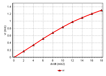
Fig. 4.7.2 Consult your manufacturer for the dynamic characteristic of his product.
4.7.5. CHECKV - undamped (dimensionless)
4.7.5.1. Hydraulic specifications
description |
input |
unit |
range |
default |
remarks |
|---|---|---|---|---|---|
inner diameter |
real |
[m] |
(0-10) |
||
loss coefficient |
real |
[-] |
[0-10] |
||
delta_p for reopen |
real |
[N/m2] |
(0-106) |
||
Dimensionless dynamic characteristic |
table |
||||
Critical velocity |
real |
[m/s] |
(0-10) |
||
initial state |
open/closed automatic |
automatic |
See also “Mathematical models” (Section 4.7.1.1). The check valve will automaticly determine if it is open or closed when it is in the initial state automatic. To determine the position it will first try the calcualtion with open check valve. If this results in return flow, it will retry with a closed check valve. If it cannot find a solution the user will be informed and need to select either the open or closed state self.
4.7.5.2. Component specific output
Dv/dt: [m/s2]
Anchor force: [N]
4.7.5.3. H-actions
None
4.7.5.4. Component messages
Message |
Type |
Explanation |
|---|---|---|
starts in closed phase |
Info |
|
starts in open phase |
Info |
|
closes |
Info |
|
opens |
Info |
4.7.5.5. Example
Type |
Checkvalve (undamped, dimless ) |
|---|---|
Comment: horizontal position; spring loaded |
|
Model name |
Nozzle type |
Inner diameter (mm) |
800.0 |
Loss coefficient (-) |
4.500 |
Delta_p for reopen (kPa) |
10.000 |
Critical velocity Vo (m/s) |
2.50 |
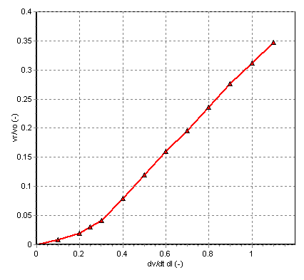
Fig. 4.7.3 A sample characteristic of a check-valve showing \(dv/dt\) versus \(v_r\)
Some typical dimensionless dynamic characteristics are shown in the picture below. These characteristics are for reference only.
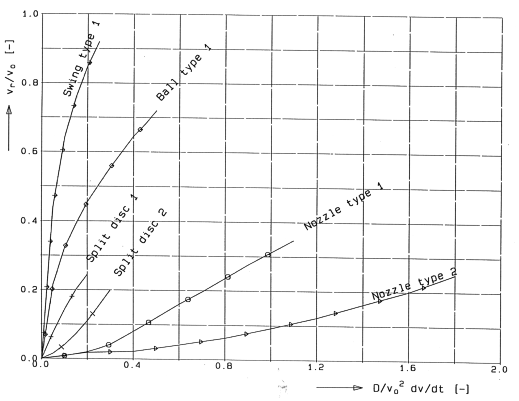
Fig. 4.7.4 Consult your check valve manufacturer for the real dynamic characteristics of his product.