4.22. PUMPSS
4.22.1. PUMPSS (class)
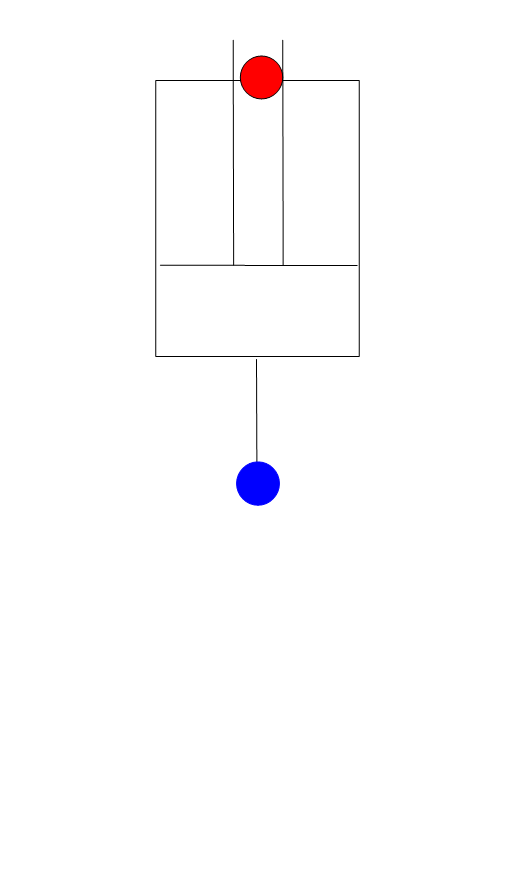
Fig. 4.22.1 Schematic of the Wanda Piston Pump component
Single cylinder, single-acting pump with mechanically driven piston
Supplier type
type label |
description |
active |
|---|---|---|
Pump Simplex, single-acting |
A single cylinder, with a mechanically driven single-acting piston.. |
Yes |
A single cylinder reciprocating pump model can be created by connecting the cylinder to the node shared by two check valves in series See Figure 1.
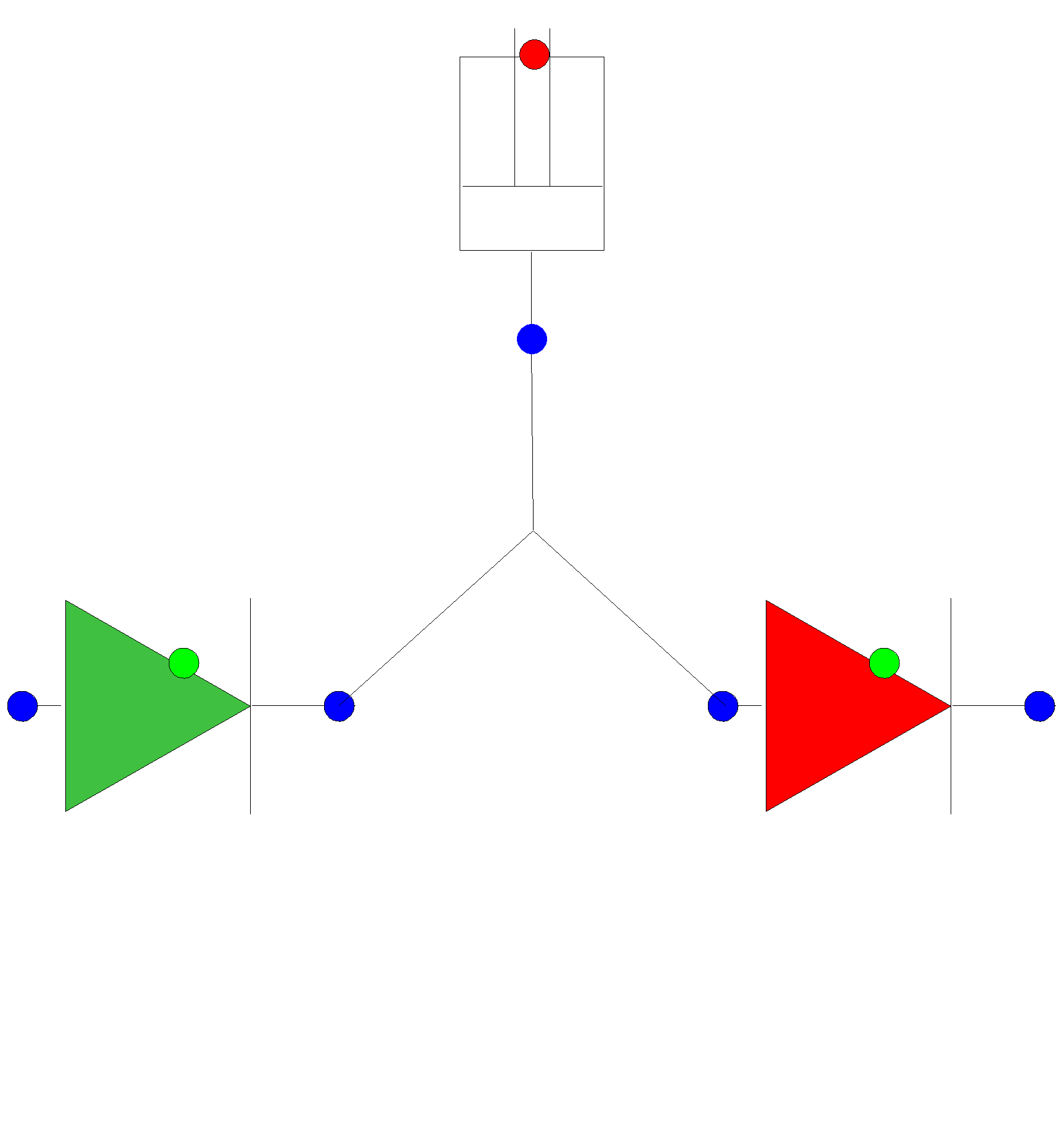
Fig. 4.22.2 Simplex, single-acting reciprocating pump model
A multi-cylinder pump model can be created by placing multiple instances of these cylinders and check valves in series
4.22.1.1. Mathematical model
Figure 2 shows the geometry of the one cylinder piston pump and its motion.
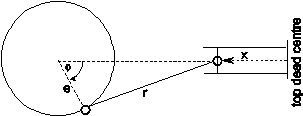
Fig. 4.22.3 Geometry of piston motion
The crank angle is defined as:
where Φ is the crank angle relative to the top dead centre (radians), ω is the constant pump speed (radians/sec), t is time and c is the crankshaft offset angle (radians). For a variable pump speed equation (4.22.1) can be rewritten as:
where n denotes the values of the present time-step, n-1 denotes the values of the previous time-step, Δt is the time-step length and x is the piston position relative to the top dead centre, e is the crank radius and r is the connecting rod length.
The piston position may also be normalized [-1,+1] as:
The cylinder volume V and piston flow rate Qp (derived from the piston position) is given by:
where VTDC is the cylinder volume at top dead centre and Ap is the piston area.
In the steady state there is no piston movement, hence no discharge is entering or leaving the cylinder. This can be written as a residual :
During motion the following continuity equation applies:
where Q is the discharge out of the cylinder, QP is the volumetric discharge of the piston, P is the pressure inside the cylinder and K is the bulk modulus of the fluid inside the cylinder. Dividing (4.22.8) by fluid density and gravity acceleration and integrating fully implicitly in time gives:
Where H is the pressure head within the cylinder.
The piston pump model does not account for cavitation occurring within the pump cylinder.
4.22.2. PUMPSS (Piston Pump)
4.22.2.1. Hydraulic specifications
Description |
input |
unit |
Range |
default |
remarks |
|---|---|---|---|---|---|
Initial motor speed |
Real |
rad/s |
|||
Initial phase |
Real |
radians |
0 - 2π |
0 |
|
Cylinder volume |
Real |
m3 |
volume at top dead centre |
||
Piston area |
Real |
m2 |
|||
Crank radius |
Real |
m |
|||
Connecting rod length |
Real |
m |
4.22.2.2. Component specific output
Motor speed [rad/s]
Piston position (normalized) [-]
Crank shaft angle [radians]
4.22.2.3. H-actions
Example:
To simulate a duplex, triplex or any other multicylinder pump, multiple instances of the PUMPSS component together with both checkvalves need to be placed parallel, with each cylinder having a unique phase angle.
The example below shows a triplex piston pump, with initial phase angle of respectively 0°, 120° and 240°.
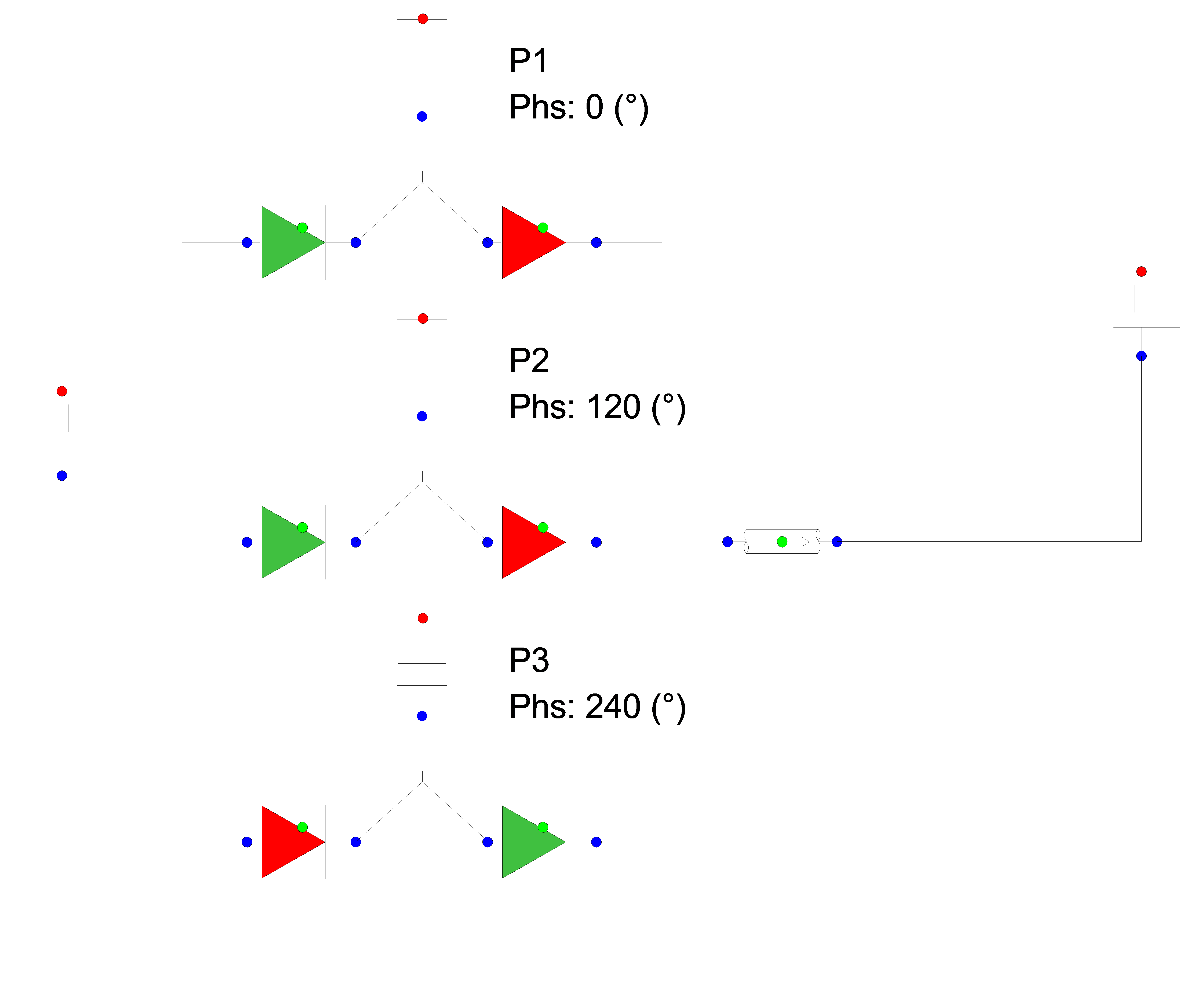
Fig. 4.22.4 Schematic overview of Wanda model
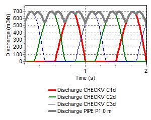
Fig. 4.22.5 Discharge of the modeled triplex piston pump.
4.22.2.4. Component messages
Message |
Type |
Explanation |
|---|---|---|
Time-step should be smaller than reciprocating pump period |
Error |
Time-step is too large |