4.11. Damper, Surge vessel
4.11.1. Damper, Surge vessel

Fig. 4.11.1 Damper, Surge vessel (vertical bladdered)
Supplier type
Type label |
description |
active |
|---|---|---|
Damper, Surge vessel |
Vertically positioned, prismatic (constant area), bladder or piston type damper |
No |
4.11.1.1. Mathematical model
The damper or surge absorber is a vessel which allows for some dynamic (temporary) liquid storage upon exceedance of a certain (filling) pressure by compressing an enclosed gas volume. The gas is separated from the liquid by a bladder or a piston, to prevent it from being dissolved in the liquid. The damper described herein is a vertical, prismatic (e.g. a standing cylinder) vessel, with constant storage area.
If during the computation the system pressure exceeds the initial filling pressure, the behaviour of the vertical damper (or accumulator) is governed by two equations. The first equation describes the behaviour of the enclosed gas:
in which:
Variable |
Description |
Units |
|---|---|---|
P |
absolute gas pressure |
N/m2 |
V |
gas volume |
m3 |
k |
Laplace coefficient |
‑ |
C |
constant |
Nm |
The Laplace coefficient (also known as polytropic exponent) depends on the thermodynamic behaviour of the gas. Isothermal expansion is described by k = 1. Adiabatic expansion is described by k = 1.4 (for air or nitrogen). In the adiabatic case the polytropic exponent is the same as the isentropic exponent (κ), also known as the ratio of specific heats cp/cv. The gas is separated from the liquid by a bladder or a piston. The constant C is based on the filling pressure and the air volume of the damper with the bladder or piston fully down.
The second equation governs the amount of supplying discharge Q:
in which Aav denotes the storage surface and xf the (effective) liquid level in the vessel with respect to the horizontal reference plane. The minus sign indicates that the vessel supplies fluid to the system when the fluid level is decreasing in time (thus a positive flow if supply to the system and a negative flow if supply to the vessel) in steady state and if the system pressure is below the initial filling pressure, the air vessel does not supply liquid. Hence in this state the governing equation is:
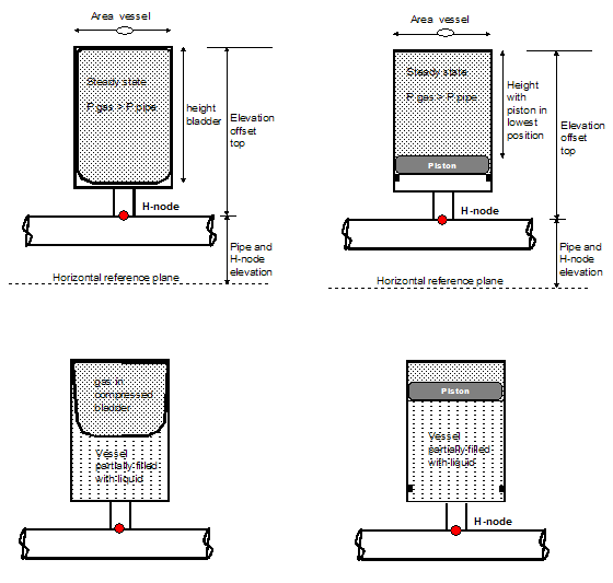
Fig. 4.11.2 Overview of surge vessels with a damper.
4.11.1.2. Hydraulic specifications
description |
Input |
unit |
range |
default |
remarks |
|---|---|---|---|---|---|
height |
real |
[m] |
See remarks |
||
area |
real |
[m2] |
(0-100] |
See remarks |
|
elevation offset top |
real |
[m] |
See remarks |
||
filling pressure |
real |
[Pa] |
Relative to atmospheric pressure |
||
Laplace coefficient |
real |
[-] |
[1-1.4] |
Remarks
The initial gas volume: Vgas = height x area
The “elevation offset top” is introduced to use the same input parameters for differently located dampers. The real elevation of the top of the vessel is determined by:
Elevation top = elevation H-node + elevation offset top
Piston weight and friction and/or bladder tension are neglected
Inlet/outlet losses are not included in this damper model, but they can be easily taken into account by applying the additional component RESIST
4.11.1.3. Component specific output
Gas pressure [N/m2.a] (Note: absolute pressure)
Gas volume [m3]
Fluid level [m]