4.6. Channel
4.6.1. Channel (class)
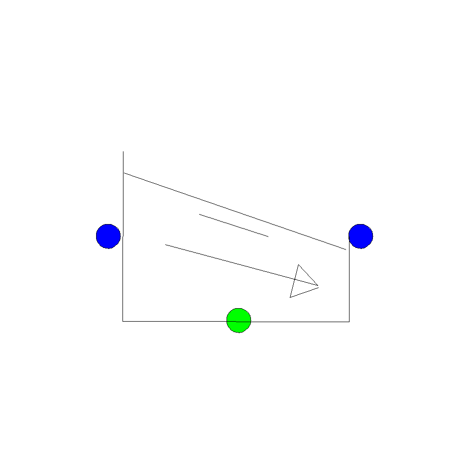
Fig. 4.6.1 Short open channel with constant slope.
The Channel component is introduced to model short open channel in waste water treatment plants (wwtp). This component is only applicable in situation with a upstream discharge boundary condition. For more complicated flow regimes, use the Free Surface Flow Conduit (PIPE conduit Q >0).
Fall type
type label |
description |
active |
|---|---|---|
Channel |
Short open channel with constant slope |
no |
Note: In transient mode, this component computes a steady-state profile for each time-step.
4.6.1.1. Mathematical model
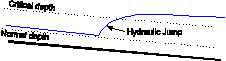
The channel model is used for continuous flow cases. It computes the upstream and downstream flow depths and velocities in a channel with constant slope (-8° to +8°, or -14% to +14%). Fig. 4.6.2 presents the definition sketch of the channel model. The flow in the channel can be shooting (supercritical) or tranquil (subcritical). For shooting flow the hydraulic control is upstream (with a depth equal or smaller to the critical depth). For tranquil flow the hydraulic control is downstream (with a depth equal to or greater than the critical depth). The channel does not account for the occurrence of a hydraulic jump (which might occur when the hydraulic control is between the upstream and downstream boundaries and the downstream boundary has a subcritical flow depth).
The geometry of the channel cross-section can be specified by the user using a depth-width table or simply by selecting a rectangular or half-round shape. Furthermore, the channel cannot overflow when the calculated flow depth exceeds the last entered depth-width table entry, since the model uses the last depth-width entry for such situations. Finally the model assumes that the flow depth is at least 1mm.
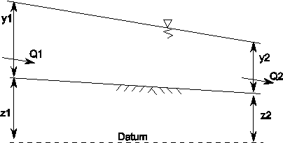
Fig. 4.6.2 Definition sketch of channel
Flow profile computation
The flow profile (and ultimately the upstream flow depth ) is computed from
with:
variable |
Description |
Units |
|---|---|---|
\(S_0\) |
Bed slope |
|
\(S_f\) |
Friction slope |
|
\(\alpha\) |
Energy coefficient |
|
\(Q\) |
Discharge |
m3/s |
\(g\) |
Gravitational acceleration |
m/s2 |
\(A\) |
Cross-sectional area |
m2 |
\(D\) |
Hydraulic depth |
m |
(4.6.1) is solved using the direct-step method. For tranquil (subcritical) flow the computation starts at a known downstream depth, while for shooting (supercritical) flow the computation starts at a known upstream depth. A default depth is assumed for the following adjacent point and its slope is computed from (4.6.1). If the slopes of the upstream and downstream points do not differ by more than 1%, then the computation proceeds to the next adjacent point. If the two slopes differ by more than 1% then the default depth of the upstream point is adjusted. Its slope is recomputed and again compared again.
Hydraulic control
In order to use (4.6.1) a known flow depth is required. From this known depth the computation proceeds upstream or downstream (depending on whether the flow is sub-or super-critical). The known flow depth is determined as follows:
For subcritical flow the flow depth at the downstream boundary is greater or equal to the critical depth, while for supercritical flow the flow depth at the upstream boundary is less or equal to the critical depth.
The critical flow depth yc is determined from
with:
variable |
Description |
Units |
|---|---|---|
\(y_c\) |
Critical flow depth |
m |
\(Q\) |
Discharge |
m3/s |
\(g\) |
Gravitational acceleration |
m/s2 |
\(A\) |
Cross-sectional area |
m2 |
\(Fr\) |
Froude number |
(4.6.2) is solved iteratively.
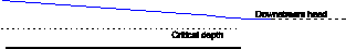
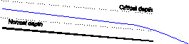
Examples of allowed flows: |
|
|---|---|
|
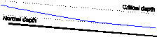
Subcritical flow with free outflow |
|
Critical flow (with submerged outflow) |
|
Critical flow (with free outflow) |
|
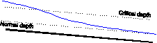
Critical flow in a long channel (normal depth is achieved) |

Examples of disallowed flows: |
|
|---|---|
|
Transitions from sub-critical to critical flow |
|
Transitions from critical to sub-critical flow (hydraulic jump) |
4.6.2. Channel
4.6.2.1. Hydraulic specifications
Description |
Input |
Unit |
range |
default |
remarks |
|---|---|---|---|---|---|
Length |
Real |
[m] |
|||
Wall roughness |
Real |
[mm] |
|||
Cross section |
rectangular / semi-circular / table |
rectangular |
|||
Width |
Real |
[m] |
If cross-section is specified as rectangular or semi-circular |
||
Depth-width table |
table |
If cross-section is specified as table |
|||
Hydraulic control |
Upstream/ Downstream |
[m] |
Upstream implies supercritical flow; Downstream implies subcritical flow |
See also “Mathematical model” (Section 4.6.1.1).
Remarks
The upstream and downstream bed levels and hence channel slope are determined by the heights of the upstream and downstream H-nodes. The slope of the channel must be less than 14% due to the constraints of the mathematical model.
The component upstream of the channel should specify a discharge (a BOUNDQ or WEIR component, for example) and not a head. The discharge through the channel should be greater than zero (i.e. the channel cannot be drained).
It the computation time takes a lot of time to solve the equation, this indicates that a wrong hydraulic control has been chosen.
4.6.2.2. Component specific output
Description |
Unit |
remarks |
|---|---|---|
Velocity upstream |
m/s |
|
Velocity downstream |
m/s |
|
Depth upstream |
m |
|
Depth downstream |
m |
|
Normal depth downstream |
m |
|
Critical depth |
m |
|
Normal depth |
m |
|
Froude upstream |
||
Froude downstream |
4.6.2.3. H-actions
None
4.6.2.4. Component messages
Message |
explanation |
|---|---|
Warning: Negative discharge not allowed. |
Flow is assumed to move in positive direction (from node 1 to node 2) |
Error: Discharge may not be zero. |
It is assumed that there is always flow in the channel. |
Error: Hydraulic head below channel bed level |
Hydraulic head cannot be lower than the channel bed level. |
Info: Slope horizontal/adverse; normal depth infinite. |
Normal depth cannot be computed since the channel slope is horizontal or adverse. |
Info: Downstream Froude <=1: Tranquil flow |
Flow is subcritical throughout the channel, except at the downstream end where it is critical or subcritical. |
Info: Downstream Froude >1: Shooting flow |
Flow is supercritical throughout the channel, except at the upstream end where it is critical or supercritical. |
Terminating Error: Slope > 14% |
Slope exceeds 14%; Check elevations of connected H-nodes. |
Literature
V.T. Chow, Open channel hydraulics, Int. ed., McGraw-Hill, Singapore, 1973.
Chanson, ‘The hydraulics of open channel flow: an introduction’, Elsevier, Amsterdam, 2004