4.30. TANK
4.30.1. TANK (class)

Fig. 4.30.1 Pressure boundary condition
Supplier type
type label |
description |
active |
|---|---|---|
TANK (constant pressure) |
Pressurised tank with constant gas pressure (e.g. floating roof tank) |
No |
4.30.1.1. Mathematical model
A TANK prescribes the pressure in a certain point of the system.
The gas pressure remains constant during the steady state and transient calculation. During the transient calculation the fluid level varies in time in accordance with net inflow into the tank. The TANK is a reasonable model, if the gas volume is relatively large (compared with the net in- or outflow during the transient calculation). If the gas volume is of the same order of magnitude as the net inflow, the component “Air Vessel” (see page 201) should be used instead.
The discharge is determined by the continuity equation for the H-node to which the TANK is connected. If a TANK is located between two pipes it actually decouples the system: the pipes are behaving independently of each other and waterhammer waves will reflect completely (reflection factor -1).
4.30.2. TANK (constant pressure)
4.30.2.1. Hydraulic specifications
description |
input |
unit |
range |
default |
Remarks |
|---|---|---|---|---|---|
Set pressure at t = 0 |
real |
[Pa] |
|||
Area |
real |
[m2] |
|||
Level bottom |
real |
[m] |
|||
Height fluid column |
real |
[m] |
See also “Mathematical model” (Section 4.30.1.1).
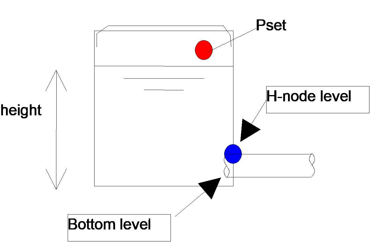
Fig. 4.30.2 Specification of variables
4.30.2.2. Component specific output
None
4.30.2.3. H-actions
None
4.30.2.4. Component messages
None