4.38. Weir
4.38.1. WEIR (class)

Fig. 4.38.1 Weir
Fall type
type label |
description |
active |
|---|---|---|
WEIR (two way) |
Broad crested weir, capable of simulating discharge in positive direction and negative direction. |
No |
4.38.1.1. Mathematical model
The component weir is often used in sewage water systems. The WEIR can have a discharge in positive or negative direction or can be closed. If the upstream head, H1, is larger than the downstream head, H2, then the WEIR will have a discharge in positive direction.
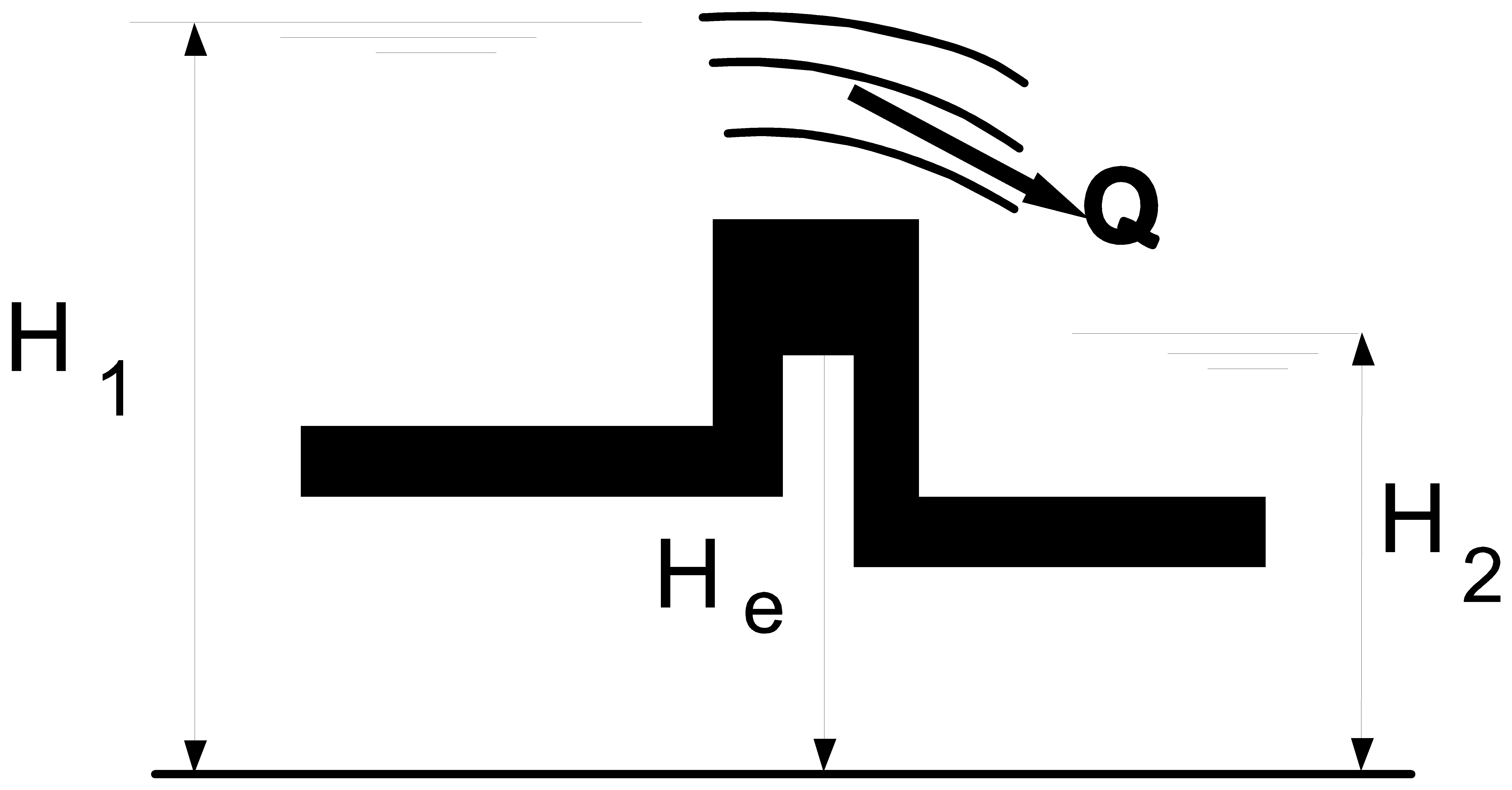
Fig. 4.38.2 Critical flow over a weir
The component can be modelled by the following equations if the flow over the edge is critical (Fig. 4.38.2):
with:
Variable |
Description |
Units |
|---|---|---|
Q1 |
Discharge through WEIR |
m3/s |
C |
Discharge coefficient |
|
B |
width of the threshold |
m |
H1 |
head upstream |
m |
He |
edge level |
m |
The first equation is only valid if the downstream head, H2, is lower than the flush criterion head and the upstream head is greater than the edge level:
and
in which H2 is the head downstream of the weir [m].
If expression (4.38.2) is violated, a warning is issued. In this case the weir behaves like a flush or submerged weir (Fig. 4.38.3) and equation (4.38.1) is no longer valid.
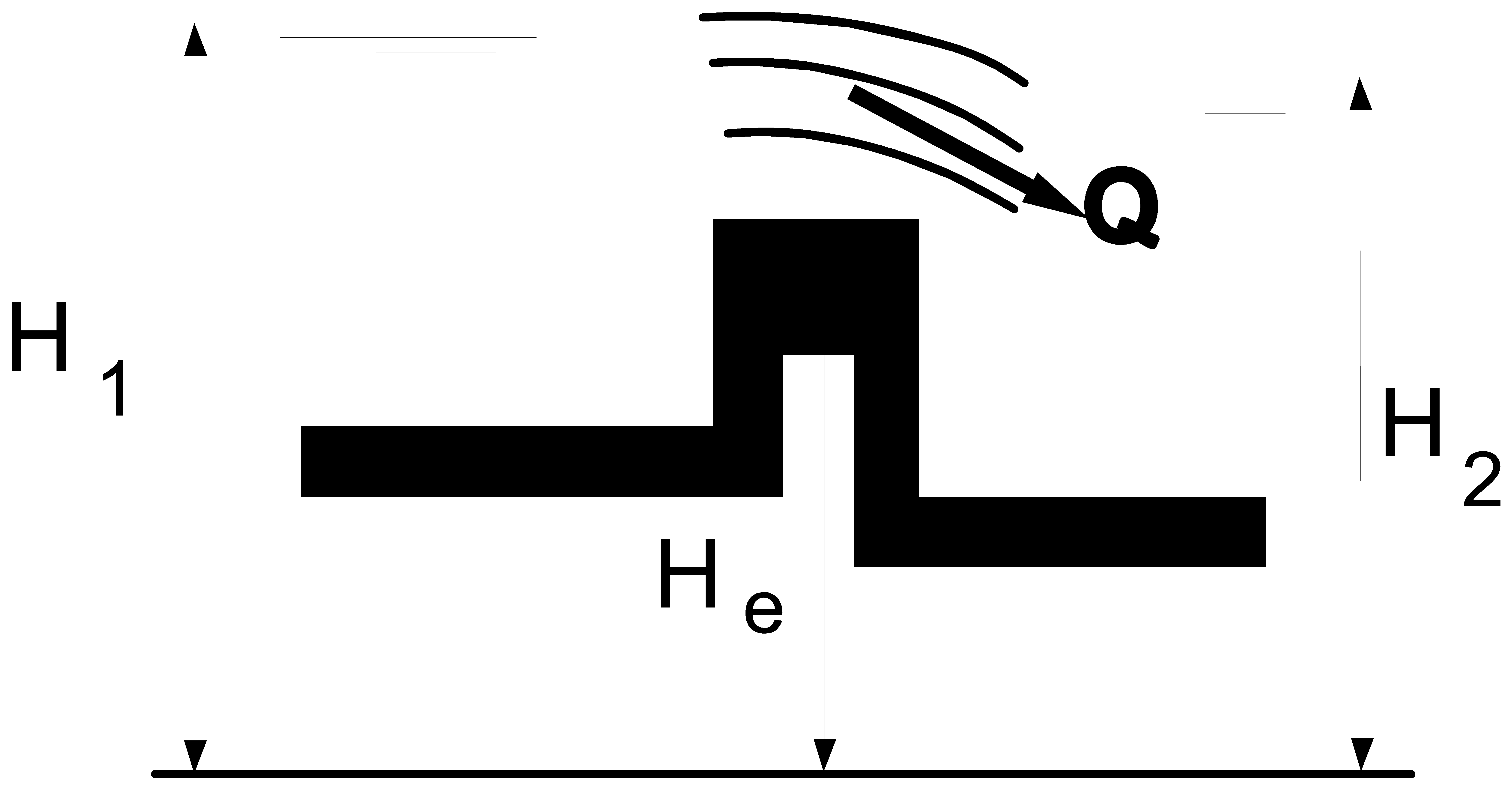
Fig. 4.38.3 Flush flow over a weir
If the weir is submerged and , the flow is no longer influenced by the weir. This situation should therefore be avoided. For a submerged weir the following equations describe the behaviour:
If expression (4) is violated, i.e. the downstream head is larger than the upstream head. The WEIR can cope with this situation and will have a discharge in negative direction. This component can be modelled by the following equations if the negative flow over the edge is critical.
This flow is critical if the upstream head is lower than the flush criterion head and the downstream head is greater than the edge level:
and
If expression (4.38.7) is violated, a message is issued. In this case the weir behaves like a flush or submerged weir. If the weir is submerged, the flow is no longer influenced by the weir. For a submerged weir with negative flow equation (4.38.6) is no longer valid. In that case the following equations are describing the behaviour:
If expression \(H_1 \geq H_e\) and \(H_2 \geq H_e\) are violated the weir runs dry (‘closes’), thus if H1 < He then
Or verbatim: there is no discharge over the weir.
In steady state the weir can be ‘open’ (H1 > He or H2 > He) or ‘closed’ (H1 <= He or H2 <= He).
Whether the weir is open or closed depends on the hydraulic state of the total system. In steady state the user must initialise the initial state of the weir (critical, submerged or closed). The program does not calculate the initial state automatically.
4.38.1.2. Discharge coefficient
Broad crested weirs
According to the literature the coefficient C in equations 1 and 2 is the product of two separate coefficients: The approach velocity coefficient Cv which corrects for the velocity upstream of the weir, and the Discharge coefficient Cd which corrects for the energy losses that occur at the weir:
The discharge coefficient must be obtained through calibration of the weir. If the discharge coefficient is unknown, an estimate can be obtained with the following equations.
The approach velocity coefficient is given by:
The water depth and velocity of the approach flow are unknown to Wanda, which means that the calculation of the approach velocity coefficient must be done by the user.
The discharge coefficient Cd corrects for the assumptions made for equation 1.
The figure below shows the relation between the ratio H1/L (the head upstream of the weir and the length of the weir) and the discharge coefficient.
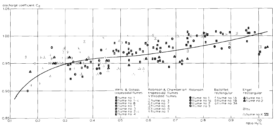
Fig. 4.38.4 Discharge coefficient as function of \(H_1/L\)
Short crested weirs
Short or sharp crested weirs are used for flowrate measurements in open channels. ISO 1438/1-1980 presents the following equation:
With:
Variable |
Description |
Units |
|---|---|---|
Q |
flow over the weir |
[m3/s] |
C |
Discharge coefficient |
[-] |
b |
width of the weir |
[m] |
H1 |
Head upstream of the weir |
[m] |
g |
gravitational acceleration |
[m/s2] |
According to ISO, the discharge coefficient is given by the following equation:
with:
Variable |
Description |
Units |
|---|---|---|
\(H_1\) |
Head upstream of the weir |
m |
p |
height of the weir |
m |
The following figure illustrates the different parameters
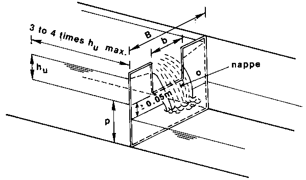
Fig. 4.38.5 Schematized weir showing the parameters that define the discharge coefficient.
The ISO equation for the discharge over the weir is not the same as the equation that Wanda uses, but this can be compensated with the discharge coefficient. To model the ISO-compliant weir in Wanda we need to use the following equation for the discharge coefficient C:
Wanda cannot solve this equation because the water depth upstream of the weir (and thus p) is unknown.
References
Bos, M.G. “The Use of Long-Throated Flumes to Measure flows in Irrigation and Drainage canals” Agricultural Water Management, 1 (1977) p111-126.
Boiten, W. “Flow measurement structures” Flow measurement and Instrumentation, 13 (2002) pag. 203-207
International Standards Organization (ISO), “Water flow measurement in open channels using weirs and venturi flumes” International Standard ISO 1438/1-1980, 1980.
4.38.2. WEIR (two way)
4.38.2.1. Hydraulic specifications
description |
Input |
Unit |
range |
default |
remarks |
|---|---|---|---|---|---|
edge level |
Real |
[m] |
|||
width |
Real |
[m] |
(0-1000] |
||
discharge coefficient |
real |
[-] |
(0-2] |
||
discharge coeff. (Q<0) |
real |
[-] |
(0-2] |
||
initial state |
critical / submerged/ closed / crit. Q<0/ subm. Q<0 |
critical |
Q<0 |
It is preferable to take an initial state of the WEIR in the steady state with a discharge in positive direction or closed.
The WEIR does not model the storage of the weir. To model both the up- and downstream storage of the WEIR, three discharges should be known. The discharge entering and leaving the WEIR are necessary to determine how much fluid stays in the storage of the WEIR. The discharge over the edge of the WEIR is necessary to determine how this fluid is divided over the up- and downstream storage. Only two of these variables can be known to Wanda, therefore it is impossible to model the storage both up- and downstream of the WEIR. It is left to the user to, if necessary, model the storage using a surge tower up- and downstream of the WEIR.
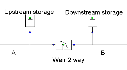
Fig. 4.38.6 Schematic model of a weir with storage.
See also “WEIR” (Section 4.38.1).
4.38.2.2. Component specific output
None
4.38.2.3. H-actions
None
4.38.2.4. Component messages
Message |
Type |
Explanation |
|---|---|---|
starts in critical state |
Info |
|
starts in submerged state |
Info |
|
starts in closed state |
Info |
|
enters critical state |
Info |
|
enters submerged state |
Info |
|
closes |
Info |
|
enters critical state, neg. flow |
Info |
|
enters submerged state, neg. flow |
Info |
4.38.3. WEIR_S (class)
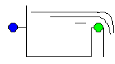
Fig. 4.38.7 Weir
Supplier type
type label |
description |
active |
|---|---|---|
Outlet WEIR (incl. storage) |
Broad-crested weir, only capable of simulating discharge in positive direction. Storage upstream of the weir is modelled. |
No |
4.38.3.1. Mathematical model
The component weir_S is often used in sewage water systems. The WEIR_S can have a discharge in positive direction or be closed. If the upstream head, H1, is larger than the edge of the WEIR_S, He, then the WEIR_S will have a discharge in positive direction. The component can be modelled by the following equations if the flow over the edge is critical (see Fig. 4.38.8):
with:
Variable |
Description |
Units |
|---|---|---|
Q |
Discharge through WEIR |
m3/s |
C |
Discharge coefficient |
m1/2/s |
B |
width of the threshold |
m |
H1 |
head upstream |
m |
He |
edge level |
m |
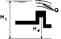
Fig. 4.38.8 Critical flow over a weir
For more information about the discharge coefficient see “Discharge coefficient” ():numref:sec_weir_discharge_coefficient).
4.38.4. Outlet WEIR (incl. storage)
4.38.4.1. Hydraulic specifications
description |
Input |
Unit |
range |
default |
remarks |
|---|---|---|---|---|---|
edge level |
Real |
[m] |
|||
width |
Real |
[m] |
(0-1000] |
||
discharge coefficient |
real |
[-] |
(0-2] |
||
Area upstream storage |
[m2] |
(0.001-500] |
|||
initial state |
critical/ dry |
critical |
The WEIR_S (with storage) is a one way weir with critical flow only. The storage upstream of the weir is modelled. This weir can only be used as boundary condition in a system.
For outlet structure the WEIR_S can be used Instead of the combination Surge tower – Weir (2-way) – Boundh;
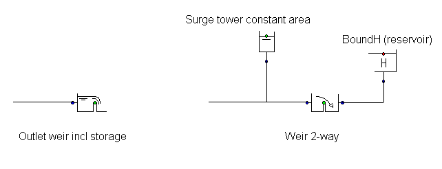
Fig. 4.38.9 Schematic representation of the outlet weir
See also “WEIR_S (class)” (Section 4.38.3).
4.38.4.2. Component specific output
Fluid level [m]
Discharge about weir [m3/s]
4.38.4.3. H-actions
None
4.38.4.4. Component messages
Message |
Type |
Explanation |
|---|---|---|
starts in critical state |
Info |
|
starts in dry state |
Info |
|
enters critical state |
Info |
|
Enter dry state |
Info |