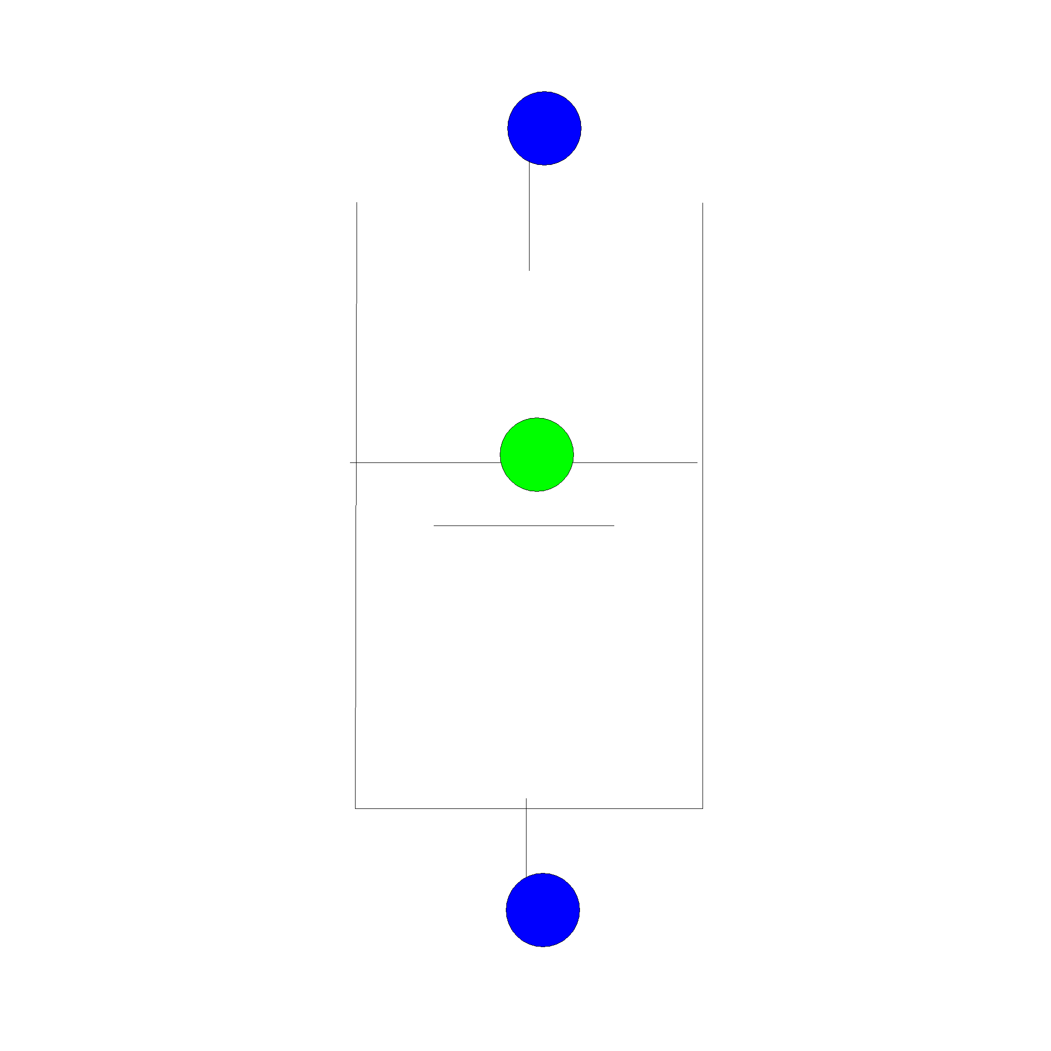
4.26. Shaft

Fig. 4.26.1 Shaft
Fall type supplier
type label |
description |
active |
|---|---|---|
Shaft |
Shaft with inflow. |
No |
The shaft models a storage element with inflows at two elevations. The edge level of the inflow at the top is an input parameter of the shaft. The other inflow is at the bottom of the shaft and corresponds to the node elevation, which should therefore be lower than the elevation of the edge level. The shaft level equals the downstream head.
A shaft is typically applied to model steep pipe sections that may drain or fill. However the pipe inertia and friction are neglected in this model. During transients the shaft behaves like a surge tower with height-dependent storage area.
4.26.1. Mathematical model
Based on the inflow over the edge, different conditions for the component can be derived:
submerged (level in the shaft, H2, above edge level, zedge)
partially filled (level in the shaft below edge level, inflow over edge)
drained at top (level in the shaft below edge level, no inflow over edge)
The basic equations governing the hydraulics of the shaft depend on the condition:
Governing equations
Furthermore, the following equations in the different states
Type |
Description |
|---|---|
Submerged: |
\(H_{1}=H_{2}>z_{\text {edge }}\) |
partially filled: |
\(H_{1}=z_{\text {edge }}\) ; \(H_{2}<z_{\text {edge }}\) |
drained at top: |
\(Q_{1}=0\) ; \(H_{1}, H_{2}<z_{\text {edge }}\) |
Head H1 is connected to the node with the inflow edge, head H2 is connected to the bottom of the shaft. zedge is the elevation of the edge level relative to the reference plane of the WANDA model. The shaft is drained at top when the head in the node H1, is lower than the edge level elevation of the shaft.
4.26.2. Hydraulic specifications
Description |
input |
unit |
range |
default |
remarks |
|---|---|---|---|---|---|
height-area table |
table |
height in metres relative to the reference plane |
|||
Initial state |
toggle |
[-] |
partially filled; submerged; Drained top; Q2=0 |
partially filled |
see below |
The initial state defines how the shaft is operated during steady state calculations, as indicated in the table below.
Initial state |
Description |
|---|---|
partially filled |
Initial shaft level is lower top edge level. Upstream head equals the top edge or is higher, such that inflow via the edge takes place. The shaft level is determined by the downstream system such that the net inflow during the steady state equals 0. |
submerged |
The shaft is pressurised if the shaft level exceeds the top edge. Upstream and downstream head are equal. The net inflow in the steady state is 0. |
Drained top |
There is no flow through the shaft. The upstream head is less than or equal to the top edge. The shaft level is determined by the downstream system. |