4.34. Vee notch Weir
4.34.1. V-weir (class)
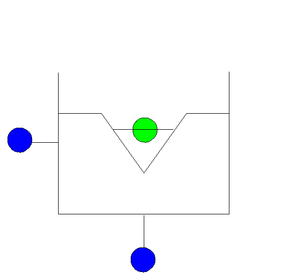
Fig. 4.34.1 Thin plate weir with one or more triangular shaped notches
Fall type
type label |
Description |
active |
|---|---|---|
Vee notch Weir |
Thin plate weir with one or more Vee shaped notches, according to ISO 1438/1 1980(E) |
no |
4.34.1.1. Mathematical model
The Vee notch weir is a short, sharp weir with one or more Vee shaped notches. The model can be used for a Vee shaped measuring weir or a Vee shaped weir of a tank.
A precondition is that the upstream fluid level is always in the V-shape and the weir discharge is independent of the downstream fluid level. So, the downstream fluid level should always below the bottom of the Vee shaped weir.
The weir discharge per Vee shape is determined by:
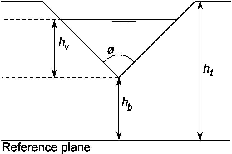
Fig. 4.34.2 Defenition sketch of the Vee notch weir
with:
Symbol |
Unit |
description |
|---|---|---|
Q |
m3/s |
Discharge per V shape |
CD |
- |
Discharge coefficient, depended on the shape of the weir. |
g |
m2/s |
Gravitational acceleration |
\(\theta\) |
˚ |
total V angle |
hv |
m |
Upstream fluid level, relative to bottom of V |
hb |
m |
Bottom level of V shape relative to reference plane |
ht |
m |
Top level of V shape relative to reference plane |
Nv |
- |
Number of V’s |
Qtot |
m3/s |
Total weir discharge |
The level of the top (ht) and bottom (hb) of the Vee notch are given relative to the reference plane.
If the upstream fluid level is above the top of the V shape (h1>ht), water flows over the whole edge. There is no critical flow anymore when the downstream fluid level is above the bottom of the V shape (h2>hb). In both cases the programme gives an error because you are outside the range of the discharge equation.
The weir is dry when the upstream fluid level drops below the bottom of the V (h1<hb). In this case:
The storage upstream of the weir is no part of the Vee notch weir component and should be modelled with another component (SURGTW).
4.34.2. Vee notch Weir
4.34.2.1. Hydraulic specifications
Description |
Input |
Unit |
Range |
default |
Remarks |
bottom V-shape |
Real |
[m] |
(-100 ; 10000] |
Downstream fluid level should be below bottom of V-shape |
|
top level V-shape |
Real |
[m] |
(-100; 10000] |
Upstream fluid level should be below top of V-shape |
|
Discharge coefficient |
Real |
[-] |
(0, 1] |
0,578 |
This is a mean value from the standard |
V-shape angle |
Real |
[˚] |
(20; 100] |
60 |
See standard |
Number of V’s |
Integer |
[-] |
(1, 1000] |
1 |
|
Initial status |
critical / dry |
critical |
See also “Mathematical model” on page 461.
4.34.2.2. Component specific output
None
4.34.2.3. H-action
None
4.34.2.4. Component messages
Message |
explanation |
Starts in critical state |
Informative: Upstream fluid level is above the bottom of the V-shape in steady state. Q>0. |
Starts in closed state. |
Informative: Upstream fluid level is below the bottom of the V-shape in steady state. Q=0. |
Closes |
Informative, weir becomes dry. |
Enters critical state |
Informative: Upstream fluid level becomes larger than bottom of V-shape. Q>0 |
Error: upstream level above top V-notch. Calculation is no longer valid |
Upstream level becomes larger than top of V-shaped notch. The calculated discharge is not correct anymore. |
Error: Return flow not allowed |
Downstream fluid level is larger than upstream fluid level; discharge in opposite direction is not allowed. |
4.34.2.5. Example
The following example demonstrates how to model a settling tank for sewage treatment works.
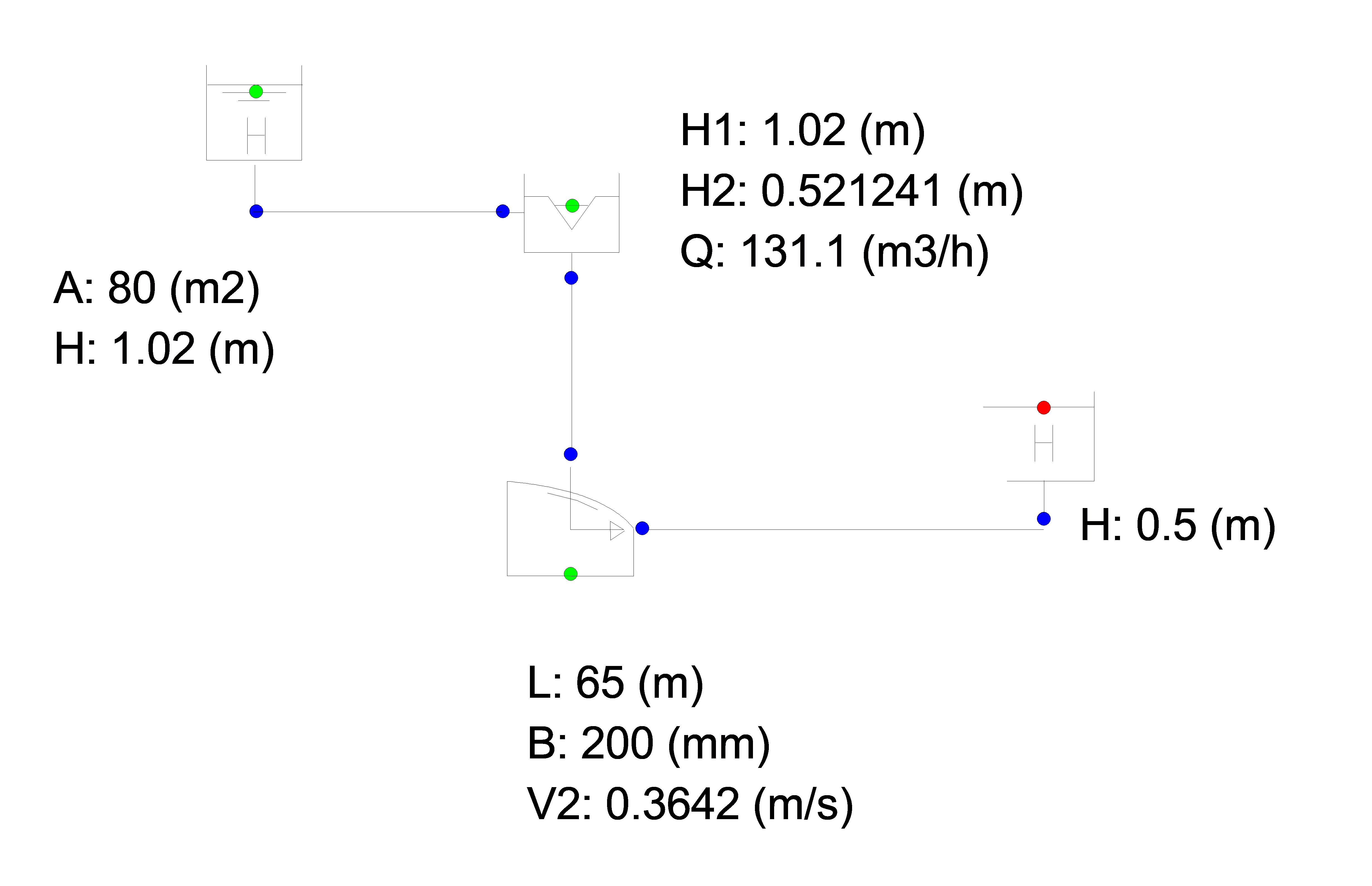
Fig. 4.34.3 Schematic Wanda model of a settling tank for a sewage treatment plant.